
Installation Guide
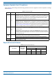
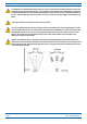
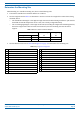
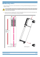
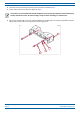
Table Of Contents
- Table of Contents
- Document Overview
- Era System Overview
- CAP H Overview
- Safely Working with a CAP H
- Installing a CAP H
- Using the Status LED to Determine State of the CAP H
- Maintenance
- Contacting CommScope

M0201AKC CommScope Era
™
High Power Carrier Access Point Installation Guide — Preliminary
© April 2019 CommScope, Inc. Page 23
Installing a CAP H
Determine the Mounting Site
When deciding on a suitable mounting site, observe the following rules.
• The CAP H is suitable for installation indoors or outdoors.
• Use the
weights listed in Table 7 to determine a site that can bear the weight of the CAP H that is being
installed, where:
– The
“Maximum Lift Weight” is the highest weight that must be lifted during installation. (An installer
should lift the CAP H components one at a time, not a wholly configured CAP H.)
– T
he “Total Hanging Weight” is the weight of the CAP H, including the weight of the Mounting Bracket,
minus the weight of the external cables and connectors, that the mounting site must be able to
support.
Table 7. Maximum CAP H Installation Weights
CAP H installed with this option … Maximum Lift Weight Total Hanging Weight
Mounting Kit Part Number kg lbs. kg lbs.
Pole 7661538 29 63.93 31 68.3
Wall 7661581 29 63.93 31 68.3
• Use the dimensions shown in Table 8 and Figure 6 on page 24 to determine the mounting site.
Table 8. Key to Figure 6 on page 24
Key Description Key Description
1 Minimum 198 mm (7.8”) 12 Minimum free space is 100 mm (3.94”) with OCTIS Kit
2 Minimum 75 mm (2.95”) 13 Minimum free space is 220 mm (8.66”) with Protective Tube Kit
3
O 12.5 mm (.5”) 14 824 mm (32.44”)
4 Power IN cable 15 782 mm (30.79”)
5 R45 min. 16 176 mm (6.93”)
6 OCTIS Kit 17
Free Area for Airflow IN
: A AIR/IN .30000 mm
2
7 Protective Tube Kit 18 20.2 mm (.80”)
8 Minimum R100mm (3.9”) 19 12 mm (.47”)
9 21.5 mm (.85”) 20 24 mm (.94”)
10 80 mm (3.15”) 21 125 mm (4.92”)
11 9 mm (.35”)