
Installation Guide
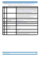
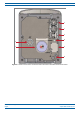
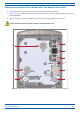
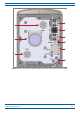
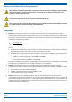
Table Of Contents
- Table of Contents
- Document Overview
- Era System Overview
- CAP H Overview
- Safely Working with a CAP H
- Installing a CAP H
- Using the Status LED to Determine State of the CAP H
- Maintenance
- Contacting CommScope

M0201AKC CommScope Era
™
High Power Carrier Access Point Installation Guide — Preliminary
© April 2019 CommScope, Inc. Page 9
CAP H Overview
Connectors and Status LED on Models with Two Antenna Connectors
• Figure 4 shows the connectors on an AC version with two antenna connectors.
• Table 3 on page 10 maps the callouts in Figure 4 and Figure 5 on page 11 and describes the connectors
and
STATUS LED.
• Figure 5 on page 11 shows the connectors on a DC version with two antenn
a connectors.
Do not remove caps from any of the connectors until instructed to do so.
1
2
3
4
6
7
5
9
8
Figure 4. Location of Connectors and Status LED on AC Version with Two Antenna Connectors