
User Manual

95
MN024-08
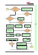
and controlled through the LMT software or through the TSUN supervision
interface.
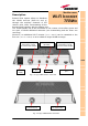
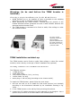
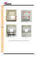
7. If the booster -48 Vdc powered (fig., use the -48 Vdc plug (included) in
order to connect the unit to the -48 Vdc mains. If the booster is 85/264
Vac-powered, fix the 85/264 Vac plug (included) on to a power cord (not
included), and use this cable in order to connect the unit to the mains. If
the TFBW booster works properly, both the green and the red LEDs should
turn on for a while and then switch off. If the LED red does not switches
off, please contact the manufacturer.
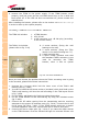
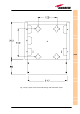
Fix the lower cover by fastening the 4 screws (fig.3.12f).
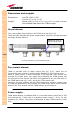
TFBW booster troubleshooting
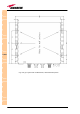
The red LED on the TFBW warm side (fig. 3.45) reveals a power amplifier bias
fault. If such a fault occurs, the alert notification is signalled also by the
switching on of the red LED on the relevant TFAx remote unit, provided that
the TFBW alarm output port has been properly connected to the TFAx external
alarm connector (fig. 3.46).
If controlled through the LMT software or through the TSUN supervision
interface, the TFBW power amplifier fault appears as an external alarm of the
TFAx remote unit to which its alarm output port is connected. Please refer to
the LMT or to the TSUN supervision manual for further details.
When the TFBW power amplifier fault is signalled by the red LED on the TFBW
booster and on its relevant remote unit, or by the LMT software or the TSUN
interface, please contact the manufacturer.
TFBW