
User Manual

94
User Manual
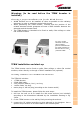
4. connect the TFBW to the power supply. If the TFBW booster works
properly, both the green and the red LEDs should turn on for a while and
then switch off. If the LED red does not switches off, please contact the
manufacturer.
After installing the booster, please refer to the section TFBW booster start-up
in order to start-up the system properly.
Installing a TFBW booster WITH the TKA01 kit
The TFBW kit includes:
The TKA01 kit includes
:
(please refer to fig. 3.44)
Once you have chosen the position where the TKA01 mounting case is going
to be mounted, please follow these instructions:
1. Unscrew the 4 screws which lock the lower cover of the TKA01 wall
bearing (see fig. 3.46a)
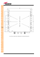
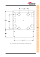
2. In order to install the M4 screw anchors (included) which shall hold up the
TKA01 wall bearing, drill into the wall according to the TKA layout shown
in fig. 3.45b.
3. Fix the TKA01 wall bearing by firmly screwing the anchors.
4. Fix the TFBW booster to the wall bearing by using the included screws
(fig. 3.46b).
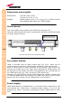
5. Connect the RF cables coming from the transmitting and the receiving
antennas to the proper RF antenna ports (fig. 3.41b). Connect the UL and
DL RF ports (fig.3.41a, 3.46c). If the TFBW booster works as a master
unit and supports a slave one, connect also the DL and UL AUX ports.
6. Connect the alarm output port (fig. 3.41a) if you want the major alarms
on the TFBW booster could be checked through the relevant remote unit
TFBW
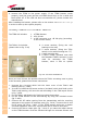
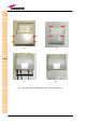
Fig. 3.44: The TKA01 installation kit
1. a TFBW booster
2. a 50 Ω load
3. a VDE connector or a -48 Vdc plug (according
to the chosen model)
A. 4 screw anchors (fixing the wall
bearing to the wall)
B. 5 screw anchors (fixing the TFAx
case A to the wall mounting box “C”)
C. A wall mounting boc
D. a splice holder (pleased note that
this standard TKA01 accessory is not
used for mounting the TFBW
booster, since it has no optical