
User Manual

93
MN024-08
Warnings (to be read before the TFBW booster is
installed)
Choosing a proper installation site for the WLAN booster
• WLAN boosters are to be installed as close as possible to the radiating
antennas, in order to minimize coaxial cable length.
• When positioning the TFBW booster, consider that the position of the
related antennas should guarantee at least a 50dB isolation between the
antennas and the booster itself
• The TFBW booster is intended to be fixed on walls, false ceilings or other
flat vertical surfaces
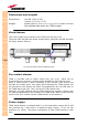
TFBW installation and start-up
The TFBW booster can be fixed on walls, false ceilings or other flat vertical
surfaces, either directly or through a TKA01 installation kit (optional).
Installing a TFBW booster WITHOUT the TKA01 kit
The TFBW kit includes:
• 1 TFBW booster
• 2 50Ω SMA loads
• 2 RF jumpers (SMA-m; N-m), 1m-long
• 1 alarm cable, 1m-long
• mains plug or -48 Vdc plug (according to the chosen model).
To install the TFBW booster, please follow the next steps:
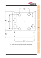
1. drill into the wall so as to install four M4 screw anchors (not included)
according to the dimensions indicated by the installation drawing in fig.
3.45a.
2. fix the TFBW booster to the wall by firmly screwing the anchors.
3. connect the RF cables according to what planned by the designer. Use a
specific torque wrench to fix each cable to the relevant ports.
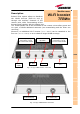
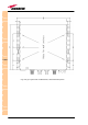
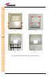
TFBW
Fig. 3.43 : (a) IEC
connector on the rear
side of a 220V
ac
-
p
owered TFBW booster.
(b) 4-pole connector on
the rear side of a -48 V
dc
-
p
owered TFBW
(a) (b)