
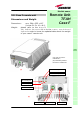
User Manual

82
User Manual
TFAx Case-F installation
Each case-F Remote Unit kit includes:
• 1 Case-F Remote Unit;
• 1 power supply cable (85 to 264 V
ac or -48Vdc, depending on the power
supply which has been chosen);
• 1 pair of mounting plates;
• 1 screw kit, including four hexagonal-head screws and a torque key.
The operations which need to be carried out in order to perform a proper
installation of the Case-F Remote Unit are hereby described:
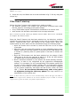
1- Drill the wall to install four M8 screws anchors (not included) as indicated
by the installation drawing shown in fig. 3.39a. Fix the two mounting plates to
the wall by firmly screwing the anchors.
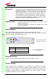
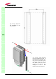
2 –Take two of the hexagonal-head screws included in the kit, and fasten
them at the top of the case-F unit (fig. 3.39b, step “1”) by using the torque
key: while fastening the screws, take care to leave the space required to
hang the case-F to the plates (fig. 3.39b, step “2”).. Fasten the screws
further only after hanging the case-F. Then take the other two hexagonal
screws (included) and use them to fasten the bottom sides of the unit to the
bottom side of the plates (fig. 3.39b, step “3”).
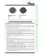
3 – Fix a splice holder (not included) inside the proper splice tray (not
included, fig. 3.38). Makes the splices between the fiberoptics patchcords
coming from the Case-F remote unit and the fiberoptics cables which go to
the local units. House the optical splices inside the splice holder. Close the
splice tray. During these operations, please take care not to bend the fibres
too much. Fix the splice tray inside a splice box (not included), and mount
the splice box beside the remote unit.
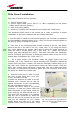
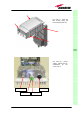
4 - Use the torque key in order to loose
the four screws fixing the cover (fig.
3.39c), and open the unit.
Connect the antenna RF cable to the RF
antenna port. Connect the UL and DL
optical connectors to the corresponding
UL and DL adapters on the unit.
Connect the Power cable to the power
connector. In case the power cable has
been connected to the mains, both the
green and the red LEDs should turn on.
The green LED will remain on to indicate
that the unit is powered on, while the
RED led will turn off as soon as the local
unit will be switched on (for further
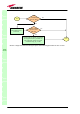
details about the start-up of the whole
system, please refer to the section ”TFAx
TFAx
CaseF
Fig. 3.38: (a) Splice tray. (b) Inside of the
splice tray, with the splice holder properly
positioned.
(
a
)
(
b
)