
User Manual

81
MN024-08
Warnings (to be read before remote units are installed)
Dealing with optical output ports
The Case-F remote unit contains semiconductor lasers. Invisible laser beams
may be emitted from the optical output ports. Do not look towards the optical
ports while equipment is switched on.
Choosing a proper installation site for the remote units
• Case-F remote units have to be installed as close as possible to the
radiating antennas, in order to minimize coaxial cable length, thus reducing
downlink power loss and uplink noise figure.
• When positioning the Case-F remote unit, pay attention that the placing of
related antennas should be decided in order to minimize the Minimum
Coupling Loss (MLC), so as to avoid blocking.
• The Case-F remote unit is intended to be fixed on walls or other flat vertical
surfaces.
Handling optical connections
• When inserting an optical connector, take care to handle it so smoothly
that the optical fibre is not damaged. Optical fibres are to be single-mode
(SM) 9.5/125µm.
• Typically, Britecell Plus equipment is provided with SC-APC optical
connectors (other connectors may be provided on request). Inserting any
other connectors will result in severe damages.
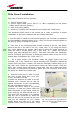
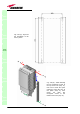
• Do not force or stretch the fibre pigtail with radius of curvature less than
5cm. See rightward figure for optimal fibre cabling.
• Remove the adapter caps only just before making connections. Do not
leave any SC-APC adapter open, as they attract dirt. Unused optical
connectors must always be covered with their caps.
• Do not touch the connector tip. Clean it with a proper tissue before
inserting each connector into the sleeve. In case connector tips need to be
cleaned, use pure ethyl alcohol.
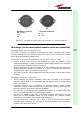
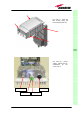
TFAx
CaseF
Figure 3.37 : (a) 85/264 Vac and (b) -36/-72 Vdc connectors on a Case-F Remote Unit
(a)
85/264Vac Connector
PE: ground
1: N
2: L
PE
1 2
4
6
(b)
-36/-72Vdc Connector
4: 0V
6: -48V