
User Manual

80
User Manual
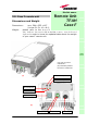
RF ports:
Optical ports:
Visual alarms:
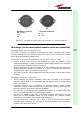
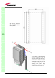
Two control LEDs are provided on the Case-F upper side (fig. 3.36).
The green LED describes the power supply status, while the red LED describes
the major Remote Unit failures (fig. 3.9).
External alarms
Case F architecture does not provide any external alarms control.
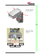
Power supply:
Case-F remote Unit is available in two versions: one feeded by universal
mains (85 to 265 Vac), the other by negative power supply (-72 to -36 Vdc):
in figure 3.37, the 85/220 Vac connector and the -72/-36 Vdc connector are
described. Power feeder is always internal. The power cable is always
included in the Case-F remote unit kit.
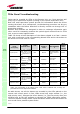
TFAx
CaseF
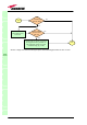
Led colour
Meaning
Red
Low optical power at DL input
and/or RF amplifier failure
Green Power supply OK
Table 3.9: summary of Case F
LEDs meaning
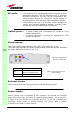
• 1 RF antenna port, transmitting/receiving signals to/from
distributed antennas. This RF antenna port is a duplexed
N-female connectors. The port can be connected to the
antenna either directly (ie. through RF jumper cables) or
through splitters, thus allowing more antennas to be fed.
• 1 RF auxiliary input and 1 RF auxiliary output (designed to
receive and transmit additional signals). Auxiliary input
and output ports are SMA-female connectors.
• 1 optical output port, transmitting UL signals to TFLN
master optical TRX;
• 1 optical input port, receiving DL signals from TFLN
master optical TRX.
Fig. 3.36 : LED panel on
the Case
F
warm side