
User Manual

73
MN024-08
ALARM
CODE
(TSUN
description)
ALARM
DESCRIPTION
ACTIVE
LED
SUPERVISION
PRIORITY
LEVEL
ACTION
RECOMMENDED
RELÉ
PRIORITY
LEVEL
(subrack)
DL optical power
The DL received
optical power is too
low and can no more
be compensated by
AGC
1
RED MAJOR
Check the DL fibre
and the TFLN laser
status
MAJOR
AGC out of
range
The DL received
optical power
experiences a loss >
3dB, which
nevertheless can still
be compensated
1
NONE WARNING
Clean optical
connectors
MINOR
External 1 alarm
Alarm on the device
connected on dry-
contact 1
RED MAJOR
Check the external
device or alarm
connection
MAJOR
External 2 alarm
Alarm on the device
connected on dry-
contact 2
RED MAJOR
Check the external
device or alarm
connection
MAJOR
Power supply
alarm
UPS HW failure or
malfunction.
RF is turned OFF
RED MAJOR
Check the external
PSU. If it works
properly, return the
unit
MAJOR
Internal BUS
alarm
A malfunctioning on
the digital part involves
a fault in monitoring
functionalities
RED CRITICAL Return the unit MAJOR
Temperature
alarm
Over-temperature
alarm
NONE MINOR
Check ventilation
and environment
MINOR
DL UMTS band
alarm
HW failure on the DL
UMTS band RF
section
RED CRITICAL Return the unit MAJOR
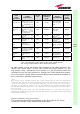
As table shows, not all the alarms are revealed by the LEDs placed on the
remote unit control panel: in fact, LEDs reveal only major alarms (i.e., the
high priority ones), whereas the minor alarms (i.e., the low priority ones) are
revealed only by the LMT software or through the TSUN supervision system.
The minor alarms usually detect critical situations which should be checked so
as to avoid future possible system faults.
1
Note:
Each remote unit is provided with an AGC system which comes in after the optical-to-RF
conversion. This AGC can correctly compensate optical losses when these are estimated to be
<3 dB. In case optical losses are in the 3dB- 4dB range, the AGC is said to be “out of range”:
the whole system still work, but AGC is near to its borderline levels. The DL power LED switches
on when the estimated optical losses are >4dB, the AGC not being able to compensate these
losses any more.
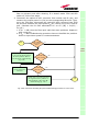
As shown in the previous table, the same red LED switches on to reveal any major failure.
Following the troubleshooting procedure reported hereinafter it is possible to better understand
what problem occurred
.
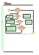
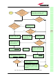
Quick troubleshooting procedure
(The following procedure is summarized by the flow-chart in fig. 3.34a)
In case the red LED is ON, please follow these steps:
TFAx
CaseL
Table 3.8: Description of the alarms of the TFAN Case-B Remote
Unit, as they are presented on LMT or Supervision Interface