
User Manual

68
User Manual
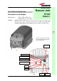
Case-L remote unit and the fiberoptics cables which go to the local units.
House the optical splices inside the splice holder. Close the splice tray. During
these operations, please take care not to bend the fibres too much. Mount
the splice tray beside the remote unit.
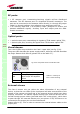
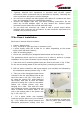
5 -Turn the key which is provided in order to open the connector cover, and
remove the connector cover as in fig. 3.33e. If you need to use the Remote
Unit to control alarms on external devices, please refer to fig. 3.30 and to the
section “external alarms” in order to perform a proper cabling of the external
alarms connections.
6 - Loosen the four screws fixing the cover (fig. 3.33f), and take the cover
off. Unscrew the three screws indicated in fig. 3.33g, and open the unit
(3.33h).
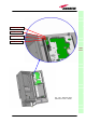
7 - Connect the antenna RF cable to the RF antenna port (refer to fig. 3.33i).
In order to meet the IP65 compliance, please follow this procedure to carry
out the optical UL / DL connections. During these operations, take care not to
bend the fibers too much.
• Take off the PG13,5 Nut, the split-seal, the PG 13,5, and the pipe
connection.
• Make the optical patchcord pass through the PG 13,5 nut, the PG 13,5 and
the pipe connection. Connect the UL and DL optical connectors to the
corresponding UL and DL adapters the unit.
• Screw the pipe connection to the unit. Fasten the PG 13,5 to the pipe
connection.
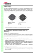
• House the fiber optic cables (Ul and DL) on one half of the split-seal.
• Close the two halves of the split-seal, while paying attention not to stretch
the fibers.
• Insert the split-seal inside the PG13,5. Screw the PG 13,5 nut onto the PG
13,5.
8 - Connect the Power cable to the power connector. In case the power cable
has been connected to the mains, both the green and the red LEDs should
turn on. The green LED will remain on to indicate that the unit is powered on,
while the RED led will turn off as soon as the local unit will be switched on
(for further details about the start-up of the whole system, please refer to the
section ”TFAx Case L start-up”).
9 - Close the cover, and fasten the 3 screws indicated in fig. 3.33g. Fasten
the 4 screws indicated in fig. 3.33f. Mount both the external cover and the
connector cover. Turn the key to close the connector cover.
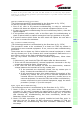
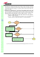
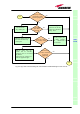
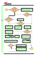
TFAx Case-L start-up
Before the Case-L remote unit is switched on, make sure that:
• the modules hosted in the master unit have been connected each other
with RF jumpers, according to the system design
• every TFLN master optical TRX has been connected to its remote units
• each remote unit has been connected to its coverage antennas
TFAx
CaseL