
User Manual

6
7
MN024-08
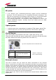
• Typically, Britecell Plus equipment is provided with SC-APC optical
connectors (other connectors may be provided on request). Inserting any
other connectors will result in severe damages.
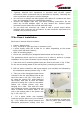
• Do not force or stretch the fibre pigtail with radius of curvature less than
5cm. See rightward figure for optimal fibre cabling.
• Remove the adapter caps only just before making connections. Do not
leave any SC-APC adapter open, as they attract dirt. Unused optical
connectors must always be covered with their caps.
• Do not touch the connector tip. Clean it with a proper tissue before
inserting each connector into the sleeve. In case connector tips need to be
cleaned, use pure ethyl alcohol.
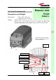
TFAx Case-L installation
Each case-L Remote Unit kit includes:
• 1 Case-L Remote Unit;
• 1 key, required to open the Case-L connector cover
• 1 power supply cable (85 to 264 V
ac or -48Vdc, depending on the power
supply which has been chosen);
• 1 pair of mounting plates;
• 1 screw kit, including four hexagonal-head screws and a torque key.
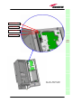
The operations which need to be carried out in order to perform a proper
installation of the Case-L Remote Unit are hereby described:
1- Take down the 2 mounting plates which are fixed to the case L (fig. 3.33a).
Fix the two mounting plates to the wall by firmly screwing the anchors.
2. Drill the wall to install four M8 screw anchors (not included) as indicated by
the installation drawing shown in fig. 3.33b.
3 –Take two of the hexagonal-head screws
included in the kit, and fasten them at the
top of the case-L unit (fig. 3.33c, step “1”)
by using the torque key: while fastening
the screws, take care to leave the space
required to hang the L-case to the plates.
Fasten the screws further only after
hanging the L-case. Then take the other
two hexagonal screws (included) and use
them to fasten the bottom sides of the
unit to the bottom side of the plates (see
fig. 3.33c, step “2”).
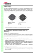
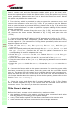
4 – Fix a splice holder (not included)
inside the proper splice tray (not included;
fig. 3.32).
Makes the splices between the
fiberoptics patchcords coming from the
TFAx
CaseL
Fig. 3.32: (a) Splice tray. (b) Inside of the
splice tray, with the splice holder properly
positioned.