
User Manual

66
User Manual
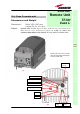
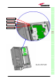
Power supply:
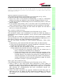
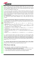
The Case-L remote Unit is available in two versions: one feeded by universal
mains (85 to 265 Vac), the other by negative power supply (-72 to -36 Vdc):
in figure 3.31, the 85/220 Vac connector and the -72/-36 Vdc connector are
described. Power feeder is always internal. The power cable is always
included in the Case-L remote unit kit
Warnings (to be read before remote units are
installed)
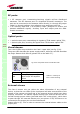
Dealing with optical output ports
The Case-L remote unit contains semiconductor lasers. Invisible laser beams
may be emitted from the optical output ports. Do not look towards the optical
ports while equipment is switched on.
Choosing a proper installation site for the remote units
• Case-L remote units have to be installed as close as possible to the
radiating antennas, in order to minimize coaxial cable length, thus
reducing downlink power loss and uplink noise figure.
• When positioning the Case-L remote unit, pay attention that the placing of
related antennas should be decided in order to minimize the Minimum
Coupling Loss (MLC), so as to avoid blocking.
• The Case-L remote unit is intended to be fixed on walls or other flat
vertical surfaces.
Handling optical connections
• When inserting an optical connector, take care to handle it so smoothly
that the optical fibre is not damaged. Optical fibres are to be single-mode
(SM) 9.5/125µm.
TFAx
CaseL
(a)
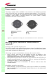
85/264Vac Connector
PE: ground
1: N
2: L
PE
1 2
4
6
(b)
-36/-72Vdc Connector
4: 0V
6: -48V
Figure 3.31 : (a) 85/264 Vac and (b) -36/-72 Vdc connectors on a Case-L Remote Unit