
User Manual

64
User Manual
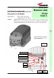
RF ports:
• 1 RF antenna port, transmitting/receiving signals to/from distributed
antennas. This RF antenna port is a duplexed N-female connectors. The
port can be connected to the antenna either directly (ie. through RF jumper
cables) or through splitters, thus allowing more antennas to be fed.
• 1 RF auxiliary input and 1 RF auxiliary output (designed to receive and
transmit additional signals). Auxiliary input and output ports are SMA-
female connectors.
Optical ports:
• 1 optical output port, transmitting UL signals to TFLN master optical TRX;
• 1 optical input port, receiving DL signals from TFLN master optical TRX.
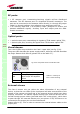
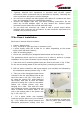
Visual alarms:
Two control LEDs are provided on the Case-L upper side (see fig. 3.29).
The green LED describes the power supply status, while the red LED describes
the major Remote Unit failures (please rfer to the table 3.7).
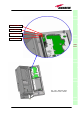
External alarms
The Case-L remote unit can collect the alarm information of any external
device, so that the two LEDs of the visual panel will take account both of the
alarms of the remote unit itself and of the external devices which have been
properly connected. The alarms signals coming from external devices can be
carried through proper cables (provided with 0.62” molex plugs), which have
to pass through the external alarms port (see picture 3.28) and have to be
connected to the proper pins on the motherboard.
Please refer to fig. 3.30 in order to connect the external alarms cables to the
proper pins.
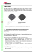
TFAx
CaseL
Led colour
Meaning
Red
Low optical power at DL
input and/or RF amplifier
failure
Green Power supply OK
Table 3.7: summary of
Case-L LEDs meaning
Fig. 3.29 : LED panel on the Case-B warm side