
User Manual

51
MN024-08
3. Fix the TKA04 wall bearing by firmly screwing the anchors.
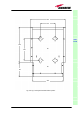
4. In order to install the M4 screw anchors (not included) which shall hold up
the power supply external adapter, drill into the wall according to the power
supply layout shown in fig.3.25b.
5. Fix the external power supply adapter to the wall by firmly screwing the
anchors.
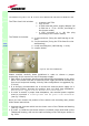
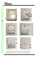
6. Carefully open the splice tray by using a screwdriver as in fig. 3.26b. Fix the
splice holder inside the splice tray (fig. 3.26c). Splice the optical fibres and
close the splice tray. While handling the fibers, take care of the fiber
bending. Close the splice tray.
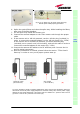
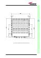
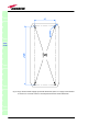
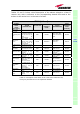
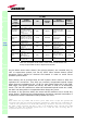
Fig. 3.24. Example of proper mounting configuration, which assures proper heat dissipation. Note
that the remote unit and its power supply adapter are mounted side-by-side, and the power supply
adapter has the socket downwards. The pictures refer to a 220 Vac – powered TFAx Case B (a)
and to a -48 Vdc –powered TFAx Case B (b).
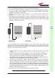
7. Fix the remote unit to the wall-bearing by using the included screws (fig.
3.26d).
8. If the remote unit is -48 Vdc powered, use the -48 Vdc plug (included) in
order to connect the external adapter to the -48 Vdc mains (fig. 3.24b).
If the remote unit is 90/264 Vac-powered, fix the 90/264 Vac plug
(included) on to a power cord (not included), and use this cable in order to
connect the external adapter to the mains (fig. 3.24a).
9. Connect the antenna RF cables to the RF antenna ports. Connect the UL
and DL optical connectors (fig. 3.26e). If the power cable has properly
been connected to the main, both the green and the red LEDs should turn
on. The green LED will remain on to indicate that the unit is powered on,
while the red LED will turn off as soon as the local unit will be switched on
(for further details about the start up of the system, please refer to the
section “TFAx Case B Start-up”)
10. Fix the lower cover by fastening the 4 screws (fig. 3.26f)
TFAx
CaseB
(a)
(b)
Universal mains
(90 to 264 Vac)
Neg. supply
(-72 to -36 Vdc