
User Manual

50
User Manual
Installation of the Case B remote unit WITH the TKA04 installation kit
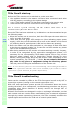
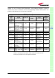
The TFAx Case B kit includes:
The TKA04 kit includes:
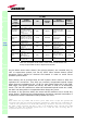
Please consider carefully these guidelines in order to choose a proper
positioning of the remote unit and of its power supply:
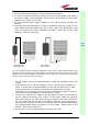
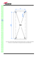
o Each piece of equipment should not be affected by the heating of any other
piece. The remote unit and its external power supply should be mounted so
as to avoid reciprocal heating. Side-by-side configuration is suggested (fig.
3.24 a,b)
o It is strongly recommended not to mount the external power supply on a
horizontal surface, because this position does not allow heat dissipation.
External power supplies must be mounted on vertical surfaces.
o In order to assure a proper heat dissipation, the external power supplies
must be mounted in vertical position with the power socket downwards
(see fig. 3.24a,b).
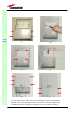
Once you have chosen the position of the remote unit mounting case, please
follow these instructions:
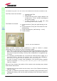
1. Unscrew the 4 screws which lock the lower cover of the TKA04 wall bearing
(see fig. 3.26a)
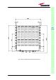
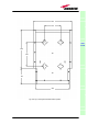
2. In order to install the M4 screw anchors (included) which shall hold up the
TKA04 wall bearing, drill into the wall according to the TKA layout shown in
fig. 3.25c.
TFAx
CaseB
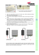
Fig. 3.23: The TKA installation kit
2. a remote unit TFAx
3. a 50 Ω load
4. a TPSN external power supply adapter (86
to 264 Vac or -72 to -36 Vdc, according to
the chosen model)
5. a VDE connector or a -48 Vdc plug
(
accordin
g
to the chosen model
)
A. 4 screw anchors (fixing the wall bearing to the
wall)
B. 5 screw anchors (fixing the TFAx Case B to the
wall bearing)
C. a wall mounting box (wall bearing + cover)
D. a splice holder