
User Manual

4
7
MN024-08
Choosing a proper installation site for the remote units
• TFAx remote units have to be installed as close as possible to the radiating
antennas, in order to minimize coaxial cable length, thus reducing downlink
power loss and uplink noise figure.
• When positioning the TFAx remote unit, pay attention that the placing of
related antennas should be decided in order to minimize the Minimum
Coupling Loss (MLC), so as to avoid blocking.
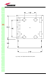
• The TFAx remote unit is intended to be fixed on walls, false ceilings or
other flat vertical surfaces (TKA installation kits are available, in order to
provide a protective cover for TFAx remote unit, while making the TFAx
installation easier and faster).
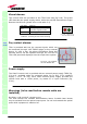
Handling optical connections
• When inserting an optical connector, take care to handle it so smoothly
that the optical fibre is not damaged. Optical fibres are to be single-mode
(SM) 9.5/125µm.
• Typically, Britecell Plus equipment is provided with SC-APC optical
connectors (other connectors may be provided on request). Inserting any
other connectors will result in severe damages.
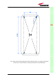
• Do not force or stretch the fibre pigtail with radius of curvature less than
5cm. See rightward figure for optimal fibre cabling.
• Remove the adapter caps only just before making connections. Do not
leave any SC-APC adapter open, as they attract dirt. Unused optical
connectors must always be covered with their caps.
• Do not touch the connector tip. Clean it with a proper tissue before
inserting each connector into the sleeve. In case connector tips need to be
cleaned, use pure ethyl alcohol.
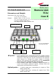
TFAx
CaseB
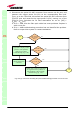
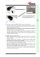
Fig. 3.20: TPSN external adapters for 220
Vac (a) and -48 Vdc (b) Case B remote
units. Power supply connector on the rear
side of Case-B remote unit (c).
Ground
Positive +5 Vdc
(a)
(c)
(b)