
User Manual

46
User Manual
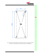
Visual alarms:
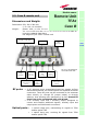
Two control LEDs are provided on the TFAx front side (fig.3.18). The green
LED describes the power supply status, while the red LED describes the major
Remote Unit failures (please refer to the table 3.4).
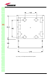
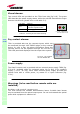
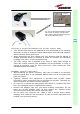
Dry contact alarms:
TFAx is provided with two dry contacts inputs, which can
be connected (through .062” MOLEX plugs) to any external
device. In such a way, the alarm information about this
external device can be signalled through the red LED of
TFAx LED panel and displayed into the supervision system.
Power supply
The Case B remote unit is provided with an external power supply TPSN (fig.
3.20 a,b), available either for universal mains (90 to 264) or for negative
supply. (-72 to -36 Vdc). Each TPSN external power supply provides the
remote units with a +5Vdc power, by means of a 3-pole connector (fig.
3.20c).
Warnings (to be read before remote units are
installed)
Dealing with optical output ports
The TFAx remote unit contains semiconductor lasers. Invisible laser beams
may be emitted from the optical output ports. Do not look towards the optical
ports while equipment is switched on.
TFAx
CaseB
Led colour
Meaning
Red
Low optical power at DL input
and/or RF amplifier failure
Green Power supply OK
Fig. 3.18 : LED panel on
the Case-B warm side
Table 3.4: summary of TFAx LEDs meaning
dr
y
contacts
Fig. 3.19 : Dry-contacts
on Case B back side