
User Manual

35
MN024-08
TFAx Case A start-up
Before the TFAx remote unit is switched on, make sure that:
• the modules hosted in the master unit have been connected each other
with RF jumpers, according to the system design
• every TFLN master optical TRX has been connected to its remote units
• each remote unit has been connected to its coverage antennas
For a correct system start-up, all the remote units have to be switched
on before the master unit.
Once the TFAx has been switched on, its behaviour can be summarized as per
the following steps:
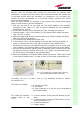
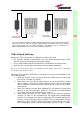
1. when the remote unit is turned on, both the LEDs upon the warm side
turn on for a couple of seconds
2. After that, the unit green LED remains on (thus indicating proper
power supply), while the red LED switches off as soon as the master
unit is turned on (meaning that DL optical power is OK and no alarms
are present).
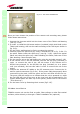
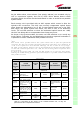
3. Once the master unit has been switched on, the status of both LEDs
have to be the one reported in table 3.1. In case the red LED remains
on, please refer to the troubleshooting section.
4. After being switched on the remote unit starts working correctly.
Anyway, in order to be recognized by the supervision management
system, it is necessary for the corresponding TFLN master optical TRX
to carry out the discovery phase (please refer to Supervision System
Manual for more details). During this phase which can last at max.
4min, depending on the system complexity, the TFLN LED ┌┘ blinks.
TFAx
CaseA
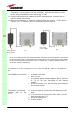
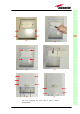
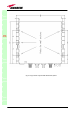
Fig. 3.14. Example of proper mounting configuration, which assures proper heat dissipation.
Note that the remote unit and its power supply adapter are mounted side-by-side, and the
power supply adapter has the socket downwards. The pictures refer to a 90/264 Vac –
powered TFAM20 (a) and to a -72/-36 Vdc –powered TFAM20 (b).
(a)
(b)
Universal mains
(90 to 264 Vac)
Neg. supply
(-72 to -36Vdc)