
User Manual

32
User Manual
(included) on to a power cord (not included), and use this cable in order
to the external adapter to the mains (fig. 3.12a).
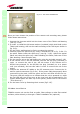
11. Connect the antenna RF cables to the RF antenna ports. Connect the UL
and DL optical connectors.
12. Once the installation is finished, please follow the section “TFAx case A
remote unit”, in order to carry out a proper system start up.
Installation of the TFAM20 remote unit WITH the TKA01 installation
kit
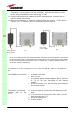
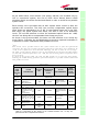
The TFAM20 kit includes:
The TKA01 kit includes
:
(
please refer to fig.
3.11)
TFAx
CaseA
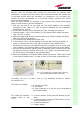
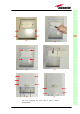
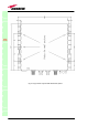
Fig. 3.12. Example of proper mounting configuration, which assures heat dissipation. Note that the
remote unit and its power supply adapter are mounted side-by-side, and the power supply adapter
has the socket downwards. The pictures refer to a 90/264 Vac – powered TFAM20 (a) and to a –
72/-36 Vdc –powered TFAM20 (b).
1. a remote unit TFAx
2. a 50 Ω load
3. an external power supply adapter (86 to 264 Vac
or -72 to -36 Vdc, according to the chosen
model)
4. a VDE connector or a -48 Vdc plug (according to
the chosen model)
A. 4 screw anchors (fixing the wall bearing to the
wall)
B. 5 screw anchors (fixing the TFAx case A to the
wall mounting box “C”)
C. A wall mounting boc
D. a splice holder
(a)
universal mains
(90 to 264Vac)
(b)
neg. supply
(
-
72 to
-
36Vdc
)