
User Manual

31
MN024-08
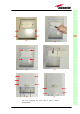
Installing a TFAM20 remote unit WITHOUT the TKA kit
The TFAM20 kit includes:
Please consider carefully these guidelines in order to choose a proper
positioning of the remote unit and of its power supply:
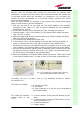
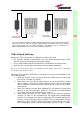
o Each piece of equipment should not be affected by the heating of any other
piece. The remote unit and its external power supply should be mounted so
as to avoid reciprocal heating. Side-by-side configuration is suggested (fig.
3.13 a,b)
o Remote units are provided with cooling fins which allow to optimize heat
dissipation. In order to let them work, the environment where the TFAM20
is mounted should allow the necessary air changeover.
o It is strongly recommended not to mount the external power supply on a
horizontal surface, because this position does not allow heat dissipation.
External power supplies must be mounted on vertical surfaces.
o In order to assure a proper heat dissipation, the external power supplies
must be mounted in vertical position with the power socket downwards (see
fig. 3.13a,b).
Once you have chosen the position of the remote unit, please follow these
instructions:
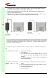
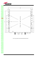
1. In order to install the M4 screw anchors (not included) which shall hold up
the TFAM20 remote unit, drill into the wall according to the case A layout
shown in fig. 3.15a.
2. Fix the TFAM20 to the wall by firmly screwing the anchors.
3. In order to install the M4 screw anchors (not included) which shall hold up
the power supply external adapter, drill into the wall according to the
power supply layout shown in fig.3.15b.
4. Fix the external power supply adapter to the wall by firmly screwing the
anchors.
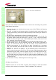
5. Take the splice – tray (not included). Fix the splice holder inside the splice
tray. (see fig. 3.10a,b)
6. Splice the optical fibres and close the splice tray. While handling the fibers,
take care of the fiber bending.
7. Fix the splice tray beside the remote unit
8. Connect the external adapter to the TFAM20 remote unit through the
9. proper cable.
10. If the remote unit is -48 Vdc powered, use the -48 Vdc plug (included) in
order to connect the external adapter to the -48 Vdc mains (fig. 3.12b).
If the remote unit is 90/264 Vac-powered, fix the 90/264 Vac plug
TFAx
CaseA
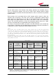
1. a remote unit TFAM20
2. a 50 Ω load
3. a TPSN external power supply adapter (90 to
264 Vac or -72 to -36 Vdc, according to the
chosen model)
4. a VDE connector or a -48 Vdc plug (according to
the chosen model)