
User Manual

30
User Manual
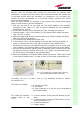
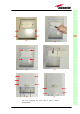
Once you have chosen the position of the remote unit mounting case, please
follow these instructions:
1. Unscrew the 4 screws which lock the lower cover of the TKA01 wall bearing
(see fig. 3.12a)
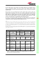
2. In order to install the M4 screw anchors (included) which shall hold up the
TKA01 wall bearing, drill into the wall according to the TKA layout shown in
fig. 3.15c.
3. Fix the TKA01 wall bearing by firmly screwing the anchors.
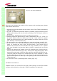
4. Carefully open the splice tray by using a screwdriver as in fig. 3.12b. Fix
the splice holder inside the splice tray. (see fig. 3.12c). Splice the optical
fibres and close the splice tray. While handling the fibers, take care of the
fiber bending. Close the splice tray.
5. Fix the remote unit to the wall bearing by using the included screws 3.12d.
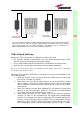
6. If the remote unit is -48 Vdc powered, use the -48 Vdc plug (included) in
order to connect the unit to the -48 Vdc mains. If the remote unit is
85/264 Vac-powered, fix the 85/264 Vac plug (included) on to a power
cord (not included), and use this cable in order to connect the unit to the
mains.
7. Connect the antenna RF cables to the RF antenna ports. Connect the UL
and DL optical connectors (fig.3.12e). If the power cable has properly been
connected to the main, both the green and the red LEDs should turn on.
The green LED will remain on to indicate that the unit is powered on, while
the red LED will turn off as soon as the local unit will be switched on (for
further details about the start up of the system, please refer to the section
“TFAx Start-up”)
8. Fix the lower cover by fastening the 4 screws (fig.3.12f).
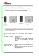
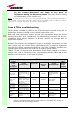
TFAM20 installation
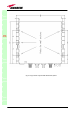
TFAM20 remote unit can be fixed on walls, false ceilings or other flat vertical
surfaces, either directly or through a TKA01 installation kit (optional).
TFAx
CaseA
Fig. 3.11: The TKA01 installation kit