
User Manual

26
User Manual
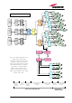
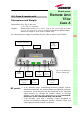
Optical ports:
Visual alarms:
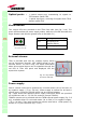
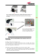
Two control LEDs are provided on the TFAx front side (see fog. 3.19). The
green LED describes the power supply status, while the red LED describes the
major Remote Unit failures (please refer to the table 3.1).
External alarms:
TFAx is provided with two dry contacts inputs, which
can be connected (through .062” MOLEX plugs) to any
external device. In such a way, the alarm information
about this external device can be signalled through the
red LED of TFAx LED panel and displayed into the
supervision system.
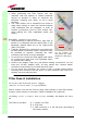
Power supply
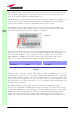
Case A remote units can be powered by universal mains (90 to 264 Vac) or
by negative supply (-72 to -36 Vdc). Power supply is internal for all Case A
remote units, except for TFAM20 which has an external adapter.
Fig. 3.9a,b shows the different power supply connectors which are provided
on 90/264 Vac and on -72/-36 Vdc versions (except TFAM20).
TFAM20 remote unit is provided with the TPSN external power supply (fig. 3.8
a,b), available either for universal mains (90 to 264) or for negative supply.
(-72 to -36 Vdc). They both provide the remote units with a +5Vdc power, by
means of a 3-pole connector (fig. 3.10c).
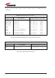
Led colour
Meaning
Red
Low optical power at DL
input and/or RF
amplifier failure
Green Power supply OK
TFAx
CaseA
dr
y
contacts
• 1 optical output port, transmitting UL signals to
TFLN master optical TRX
• 1 optical input port, receiving DL signals from TFLN
master optical TRX
Table 3.1: summary of TFAx LEDs meaning
Fig. 3.5 : LED panel on
the Case-A warm side
Fig. 3.6 : Dry-contacts
on Case A back side