
User Manual

24
User Manual
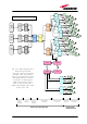
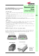
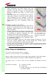
Depending on the bands where the radio coverage has to be provided and on
the required signal power to cover the environment, your remote unit can
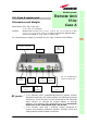
have one of the topologies shown in figure 3.1.
The following 4 sections of the manual refers to these 4 different topologies of
remote units. Please follow the instructions described in the section which
exactly corresponds to the case (A,B,L,F) of your remote unit.
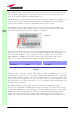
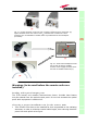
The output powers and coverage bands of each remote unit are uniquely
associated to model codes which you can easily read on both on the remote
unit and on its package box (see picture 3.2 below).
The case of your remote unit can be easily identified from the pictures 3.1: as
an alternative, you can refer to the Britecell Plus Bulletin PA-100595EN or to
the dedicated Bulletin of your remote unit. For example, let’s refer to the
Model Number “TFAM20” we read on our remote unit’s label, like in the
Ficture 3.2. On the Britecell Plus bulletin PA-100595EN, we read:
This line states that the remote unit whose model is TFAM20 has a case A
architecture (see picture 3.1), manages UMTS (2100 MHz) signals, and works
with Medium output powers. Once we identified the case of our remote unit
(case A, in this example), let’s refer to this manual’s section which exactly
corresponds to our remote unit case, so as to perform proper installation and
maintenance procedures.
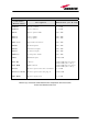
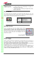
Each Britecell Plus remote unit belongs to one of the following 3 power
classes: Low, Medium and High Power. Once we know the Power Class of our
remote unit (Medium, in our example), and its working bands (e.g. 2100 MHz
UMTS), we can look through the remote unit dedicated bulletin (described
under the column “Details in bulletin”: PA-100592EN, in our example) in
order to get all the technical specifications concerning the remote unit itself.
TFAx
(Intro)
Figure 3.2
Figure 3.3
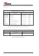
Band Configurations
Power Class
Case
Model Code
UMTS2100 Medium A TFAM20 PA-100592EN
Details in Bulletin