
User Manual


18
User Manual
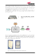
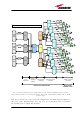
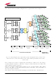
The scheme of this network configuration is reported hereafter in figure 2.19.
Fig. 2.19: Block diagram for a triple-band system with duplexed base stations. This
scheme involves a rack-based Master Unit, with 8-TFLN optical TRXs and 32 TFAx
remote units.
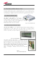
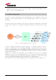
Let’s assume we need to expand our network in a wider area, by using a
second subrack station at a distance of up to 20 km from the site where the
main subrack station is located.
This new network configuration requires to use an interconnect link, whose
master side will be at the main subrack station, and whose slave side will be at
the new remotised station.
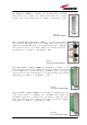
The scheme of this new network topology is shown hereafter, in figure2.20.
TLCN2
TLTN
TBSI
TBSI
TBSI
TDPX
91
TDPX
20
TDPX
18
GSM
900
BTS
GSM
1800
BTS
UMTS
BTS
DL - UL
splitting /
combining
Level
adjustment
Services
combining /
splitting
Signal splitting /
combining
Electrical / optical
conversion
Optical/electrical
conversion
3 km max
optical link
Triple-band system – duplexed BTSs – 8 TFLN
Fixed
Atten.
Fixed
Atten.
Fixed
Atten.
TLCN4
TFLN
TFAx
TFLN
TFLN
TFLN
TFLN
TFLN
TFLN
TFLN
TLCN4
TFAx
TFAx
TFAx
TFAx
TFAx
TFAx
TFAx
TFAx
TFAx
TFAx
TFAx
TFAx
TFAx
TFAx
TFAx
TFAx
TFAx
TFAx
TFAx
TFAx
TFAx
TFAx
TFAx
TFAx
TFAx
TFAx
TFAx
TFAx
TFAx
TFAx
TFAx
Britecell Plus MASTER UNIT
Britecell Plus
REMOTE UNITS