
User Manual


108
User Manual
RU4 dry-contact
functionality
RU1 External 2
alarm
External 2 alarm from
RU1
RU1 MAJOR
Check the external
device connected to
external 2 and the
RU1 dry-contact
functionality
CLOSED
RU2 External 2
alarm
External 21 alarm from
RU2
RU2 MAJOR
Check the external
device connected to
external 2 and the
RU2 dry-contact
functionality
CLOSED
RU3 External 2
alarm
External 2 alarm from
RU3
RU3 MAJOR
Check the external
device connected to
external 2 and the
RU3 dry-contact
functionality
CLOSED
RU4 External 2
alarm
External 2 alarm from
RU41
RU4 MAJOR
Check the external
device connected to
external 2 and the
RU4 dry-contact
functionality
CLOSED
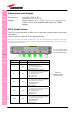
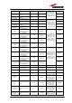
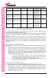
The previous table reports a brief description of the TFLF alarms, together with a
reference to the corresponding alerted LEDs.
As the table shows, all major alarms are signalled also closing the dry contacts available
on the TFLF allowing sending this information to any external equipment (i.e. BTS or
repeater)
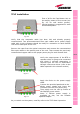
One of the LEDs RU1, 2, 3, 4 might turn on not only to indicate a high optical loss
detected by the TFLF, but also to reveal a remote unit failure. Understanding the reason
why one of this LEDs is on (a remote unit failure, an optical cable fault or an external
equipment malfunction) can be done following the troubleshooting procedure reported
hereinafter.
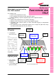
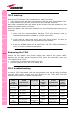
Quick troubleshooting procedure
(The following troubleshooting procedure is summarised by the flow-chart in
fig. 4.7a)
1. In case the TFLF general alarm (LED LU) is on replace the faulty TFLF
master unit with a new one and contact the manufacturer for assistance.
2. In case one of the LEDs RU1, 2, 3 or 4 is on, the corresponding TFLF
adapter might be dirty. Try cleaning it using pure ethyl alcohol. If the
LED is still on go to the corresponding remote unit side and check the
red LED upon the warm side:
a. If it is off, the optical cables or the optical connections are
supposed to have some problem on UL path. Refer to fibre optic
UL troubleshooting for more information (fig. 4.7b).
b. If it is on, refer to remote unit troubleshooting presented in the
previous remote unit section
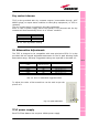
Fiber optic UL troubleshooting
(The following procedure is summarized by the flow-chart in fig. 4.7b)
1. Check if there is any point where the fibre experiences a small radius of
curvature. In this case, rearrange the optical path in order to avoid
sharp bends (if necessary, replace the optical cable with a longer one). If
this makes the TFLF LED switch off, troubleshooting has been successful.
Otherwise, follow next steps.
TFLF
Tab. 4.4: TFLF alarm descri
p
tion