
User Manual


105
MN024-08
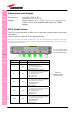
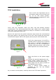
TFLF installation
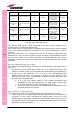
First of all fix the Fast Master Unit to
the wall by means of four screws (see
fig. 4.5 for wall anchor quotes).
Vertical position is suggested for ease
thermal dissipation.
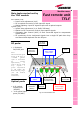
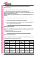
Verify that the composite cable has been laid and already properly
connectorised. Two preconnectorised fibre optic cables and a power supply
cable with 4-pole connector should be ready for connection to each Remote
Unit and to each port of the TFLF.
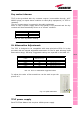
Remove the caps from the optical connectors and connect the connectorised
fibre optic cables to the optical ports of the unit. Then connect the previously
connectorised copper cable to the proper power plug for each Remote Unit.
Verify the output power of the BTS or
repeater which is going to be connected
and check if external attenuation is
required then set the UL attenuation
through a flat screw driver (refer to the
table reported in the relevant section)
Apply the ferrite to the power supply
cable.
Connect the provided patchcord to the -
48Vdc power supply and insert the
connector into the TFLF power plug.
Then switch one the unit by means of
the ON/OFF power switch.
Note: if 220Vac power supply is
available on site, use the suitable
optional adapter.
As you switch on the system, carefully refer to the TFLF Start-Up section.
TFLF
Fig. 4.4
Fig. 4.4
Fig. 4.4