
User Manual


101
MN024-08
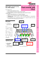
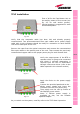
Main tasks carried out by
the TFLF module
Downlink (DL):
¾ Power level adjustment (ALC)
¾ RF-to-optical conversion of the input RF signal
¾ Optical splitting: input RF signal is split onto 4 optical outputs
Uplink (UL):
¾ Uplink Gain adjustment (0 to 20dB, 5dB step)
¾ Optical-to-RF conversion of the 4 input optical signals
¾ Automatic Gain Control (AGC) of each converted signal to compensate
optical losses
¾ RF combining of the 4 adjusted signals into a single RF path then they
are filtered and duplexed into the RF port.
RF ports:
¾ 1 Duplexed
DL/UL RF port
Note:
The maximum input
levels at RF ports is
+27dBm (please
refer to datasheet
for further
information), as
well as the UL path
may require a
power adjustment
to fill within the
BTS receiving range
(use the built-in
adjustable
attenuator).
Optical ports
¾ 4 DL optical
output ports
(SC/APC)
¾ 4 UL optical input
ports (SC/APC)
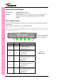
TFLF
Power Supply
Switch
Power Supply
Connector
(-48Vdc)
Alarm
Contacts
Optical UL and
DL Connectors
to Remote Units
DL/UL RF
Port to BTS
Remote Unit
Power Supply
Connectors
Master Unit
alarm and
status LEDs
UL Step
A
ttenuator
Store
Button
Remote Units
alarm and link
status LEDs
Fig. 4.1 Fast Remote Unit
Module name:
Fast remote unit
TFLF