PLU S User Manual MN024-08
© Copyright Andrew Wireless Systems Srl Andrew Wireless Systems Srl Via Pier De Crescenzi 40 48018 Faenza, Italy Tel: +39 0546 697111 Fax: +39 0546 682768 www.andrew.com This publication is issued to provide outline information and is not aimed to be part of any offer and contract. The Company has a policy of continuous product development and improvement and we therefore reserve the right to vary information quoted without prior notice.
INDEX 0. Index 2 1. Introducing Britecell Plus 1.1 The Features 1.2 Brief Description of Britecell Plus 1.3 Britecell Plus features 1.4 Britecell Plus typical applications 4 5 5 6 7 2. Equipment Overview 2.1 The Britecell Plus Remote Unit and its relevant accessories 2.2 the Britecell Plus Master Unit 2.2.1 The Fast Master Unit 2.2.2 The Rack-based Master Unit 2.3 Block diagrams 9 10 12 12 12 16 3. TFAx Remote Unit 3.1 Introduction 3.2 Case A remote unit 3.3 Case B remote unit 3.
6.5 6.6 6.7 6.7 Safety and Precautions for Lasers Health and Safety Warnings Electromagnetic Fields and RF Power Warning Labels 226 226 227 230 7. Technical support 7.
1.
1.1 The Features Britecell Plus is an innovative platform designed in order to provide an effective and flexible coverage to a large variety of indoor scenarios. Thanks to its high modularity, its low power consumption, and its fulltransparency to protocols and modulation formats, Britecell Plus is the perfect plug&play solution to distribute any wireless standard (including GSM, GPRS, EDGE, CDMA, WCDMA, and WLAN IEEE 802.
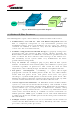
12 4 BTS RF interface TFLN 1 Two F.O. per RU REMOTE UNIT 1 Fig. 1.1: Britecell Plus system block diagram. 1.3 Britecell Plus Features The following lines report a brief summary of Britecell Plus main features: 6 • multiband 2G, 2.5G and 3G – 802.11b WLAN compatible: Britecell Plus is completely transparent to any transmission protocol and modulation format, and it can distribute any 2G, 2.5G, 3G wireless standard. In addition, it allows to carry also the WLAN (802.
• remote power supply: in case mains cannot be used for the Remote Units, Britecell Plus offers a centralised power supply option, which distributes both a DC low-voltage (-48V) power and the optical signals through a composite fibre optic/copper cable; • wide variety of RF passive devices: the connections between the DAS and the local BTSs can be arranged so as to get the best fit for customers needs.
under all conditions, while maintaining maximum flexibility in managing any traffic condition. • 8 Subways and Highly Dense Metropolitan Areas: These areas are distinguished by large distances, and may require that RUs are placed far away from the BTSs. Britecell Plus guarantees the signal integrity at distances up to 3 km, and through the wideband interconnect link option distances of 20 km can be reached.
2.
2.1. Introduction Basically, a Britecell system is composed of: • a Master Unit, able to bring mobile radio signals from the BTS to different remote units and vice-versa, so as to remotise the distribution and collection of any mobile and wireless signal; • a variable number of Remote Units, conveying and receiving mobile signals by low-power antennas.
Power supply (available either in 90÷264 Vac or in -72÷-36 Vdc version) is internal in Case L, in Case F and in most Case A remote units: vice-versa, all Case B and some Case A remote units are provided with an external power supply (TPSN), whose dimensions are shown in table 2.1(a). The TFBW unit is a booster which can be cascaded with a TFAx in order to distribute Wi-Fi signals (802.11b and g) through dedicated Wi-Fi antennas (see scheme 2.2b). (a) Fig. 2.
2.3. The Britecell Plus Master Unit The Britecell Plus Master Unit is a widely-flexible system. It is available both as a stand-alone version (the Fast Master Unit) and as a rack-based version. In the followings we will give a brief overview of the components of these units. 2.3.1 The Fast Master Unit The Master Fast (TFLF): designed into a stand-alone mechanical case, it includes all required ancillary and support functions.
The duplexer (TDPX): it combines the downlink (DL) and uplink (UL) paths into a single one, while maintaining the required isolation. The module dimensions are: Width = 7TE, Height = 4HE. Fig. 2.7: The TDPX duplexer The variable RF attenuators (TBSI): it provide independent attenuations (adjustable from 0 to 30dB, with 1dB steps) on uplink and downlink RF paths, and allow the designer to optimize the signal level close to the BTSs.
The RF splitters/combiners (TLCN2 and TLCN4): TLCN2 is a 2-way splitter/combiner. TLCN4 is a 4-way splitter/combiner. They can be used in a variety of different situations, such as: • To connect a BTS with several master optical TRXs. In uplink the TLCN2 (or TLCN4) combines 2 (4) RF signals coming from different master optical TRXs onto a common RF signal, entering the BTS.
The interconnect-link (TILx) is a multi-module kit which allows to expand our system by connecting an additional Britecell Plus subrack station to the main one, at a distance of up to 20 km. In details: • The TDTX and TMRX cards make up the “master side” of the i-link; thus, they have to be housed inside the main Britecell Plus subrack, and take 1 slot each; Fig. 2.
supply 0.5A per port: it can feed only single and dual band TFAN remote units, as well as the TFAM20 one. 2.4. Block diagrams In order to better understand the functionalities of the different units and modules, some block diagrams of the Britecell Plus system are reported hereafter. Systems based on Fast Master Unit must be directly connected to the BTS station. The scheme of a typical Fast Britecell system is reported here in fig. 2.17.
TFAx TFAx TFLN TFAx Triple-band system – not duplexed BTSs – 8 TFLN local units TFAx TFAx TFAx TFLN TFAx GSM 900 BTS Fixed Atten. TFAx TFAx TLCN4 TBSI TFAx TFLN TFAx TFAx TFAx TFAx TFLN TFAx GSM 1800 BTS Fixed Atten. TFAx TBSI TLTN TFAx TLCN2 TFAx TFLN TFAx TFAx TFAx UMTS BTS TFAx TFLN Fixed Atten.
The scheme of this network configuration is reported hereafter in figure 2.19. TFAx TFAx TFLN TFAx TFAx Triple-band system – duplexed BTSs – 8 TFLN TFAx TFAx TFLN TFAx GSM 900 BTS Fixed Atten. TDPX 91 TFAx TFAx TBSI TLCN4 TFAx TFLN TFAx TFAx TFAx TFAx TFLN GSM 1800 BTS Fixed Atten. TDPX 18 TFAx TFAx TBSI TLTN TLCN2 TFAx TFAx TFLN TFAx TFAx TFAx TFAx TFLN UMTS BTS Fixed Atten.
TFAx TFAx TFLN Triple-band system – duplexed BTSs – i-link TFAx TFAx TFAx TFAx TFLN TFAx GSM 900 BTS TDPX 91 TFAx TFAx TBSI TLCN4 TFAx TFLN TFAx TFAx TFAx TFAx TFLN GSM 1800 BTS TDPX 18 TFAx TFAx TBSI TLTN TLCN2 TFAx TFAx TFLN TFAx TFAx TFAx TFAx TFLN UMTS BTS TDPX 20 TFAx TFAx TBSI TFAx TLCN4 TFAx TFLN TFAx TFAx Fig. 2.20: Block diagram for a Britecell system with remotised station connected through i-link.
Lastly, the next tables show a brief overview of the available Britecell equipment: REMOTE UNITS and accessories Unit name/ Module name TFAx TFAx TFAx TFAx case case case case A B L F Description Remote Remote Remote Remote unit unit unit unit Dimensions (L x W x H) 240 240 455 546 x x x x 200 240 255 253 x x x x 38 38 167 207 (mm) (mm) (mm) (mm) TFBWx WLAN booster 240 x 200 x 38 (mm) TKA01 TKA04 Remote Unit installation kit Remote Unit installation kit 280 x 240 x 55 340 x 240 x 55 (mm)
RACK-BASED MASTER UNIT Unit name/ Module name Description Dimensions (L x W x H) TPRN04 TPRNx4 Passive subrack Active subrack 19” x 4HE 19” x 4HE TFLNx Master Optical TRX 7TE x 4HE TLCN 2 TLCN 4 2-way splitter 4-way splitter 7TE x 4HE 7TE x 4HE TBSI 2-30 Adjustable attenuator 7TE x 4HE TDPXx UL/DL duplexer 7TE x 4HE TLDNx TLTNx Dual band coupler Tri band coupler 7TE x 4HE 7TE x 4HE TMPx-10 10 dB power limiter 7TE x 4HE TWLI WLAN interface 14TE x 4HE TILx-HL i-link kit TILx-HLW
3.
Module name: Remote Unit 3.1.
Depending on the bands where the radio coverage has to be provided and on the required signal power to cover the environment, your remote unit can have one of the topologies shown in figure 3.1. The following 4 sections of the manual refers to these 4 different topologies of remote units. Please follow the instructions described in the section which exactly corresponds to the case (A,B,L,F) of your remote unit.
Module name: Remote Unit 3.2. Case A remote unit TFAx Case A Dimensions and Weight: Dimensions: 38 x 240 x 200 mm (1.5 x 9.4 x 7.9 inches) Weight : please refer to the Britecell Plus bulletin PA-100595EN or to the remote unit dedicated bulletin in order to know the updated data about the weight of your case A remote unit An external power supply is provided only for Case A remote unit TFAM20.
Optical ports: • • 1 optical output port, transmitting UL signals to TFLN master optical TRX 1 optical input port, receiving DL signals from TFLN master optical TRX Visual alarms: Two control LEDs are provided on the TFAx front side (see fog. 3.19). The green LED describes the power supply status, while the red LED describes the major Remote Unit failures (please refer to the table 3.1). Led colour TFAx CaseA Red Fig. 3.
(a) (b) Fig. 3.7 : (a) IEC connector on the rear side of a 220Vac-powered case A remote unit. (b) 4-pole connector on the rear side of a -48 Vdc -powered case A remote unit. These connectors are not available on TFAM20, which is provided with an external adapter (see below). TFAx CaseA Ground Positive +5 Vdc (a) (c) Fig. 3.8 : TPSN external adapters for 220 Vac (a) and -48 Vdc (b) TFAM20 versions. Power supply connector on the rear side of TFAM20 remote unit (c).
• • TFAx CaseA When positioning the TFAx remote unit, pay attention that the placing of related antennas should be decided in order to minimize the Minimum Coupling Loss (MLC), so as to avoid blocking. The TFAx remote unit is intended to be fixed on walls, false ceilings or other flat vertical surfaces (TKA installation kits are available, in order to provide a protective cover for TFAx remote unit, while making the TFAx installation easier and faster).
Remote units are provided with cooling fins which allow to optimize heat dissipation. In order to let them work, the environment where the remote unit is mounted should allow the necessary air changeover. Do not place any remote unit face downwards on a horizontal surface, because this would prevent heat dissipation. Once you have chosen the position of the remote unit, please follow these steps in order to carry out the installation: 1.
Fig. 3.11: The TKA01 installation kit TFAx CaseA Once you have chosen the position of the remote unit mounting case, please follow these instructions: 1. Unscrew the 4 screws which lock the lower cover of the TKA01 wall bearing (see fig. 3.12a) 2. In order to install the M4 screw anchors (included) which shall hold up the TKA01 wall bearing, drill into the wall according to the TKA layout shown in fig. 3.15c. 3. Fix the TKA01 wall bearing by firmly screwing the anchors. 4.
Installing a TFAM20 remote unit WITHOUT the TKA kit The TFAM20 kit includes: 1. a remote unit TFAM20 2. a 50 Ω load 3. a TPSN external power supply adapter (90 to 264 Vac or -72 to -36 Vdc, according to the chosen model) 4. a VDE connector or a -48 Vdc plug (according to the chosen model) Please consider carefully these guidelines in order to choose a proper positioning of the remote unit and of its power supply: o Each piece of equipment should not be affected by the heating of any other piece.
(included) on to a power cord (not included), and use this cable in order to the external adapter to the mains (fig. 3.12a). 11. Connect the antenna RF cables to the RF antenna ports. Connect the UL and DL optical connectors. 12. Once the installation is finished, please follow the section “TFAx case A remote unit”, in order to carry out a proper system start up. TFAx CaseA neg. supply (-72 to -36Vdc) universal mains (90 to 264Vac) (a) (b) Fig. 3.12.
TFAx CaseA (a) (b) (c) (d) (e) (f) Fig. 3.
TFAx CaseA Please consider carefully these guidelines in order to choose a proper positioning of the remote unit and of its power supply: o Each piece of equipment should not be affected by the heating of any other piece. The remote unit and its external power supply should be mounted so as to avoid reciprocal heating. Side-by-side configuration is suggested (fig. 3.
Universal mains (90 to 264 Vac) (a) Neg. supply (-72 to -36Vdc) TFAx CaseA (b) Fig. 3.14. Example of proper mounting configuration, which assures proper heat dissipation. Note that the remote unit and its power supply adapter are mounted side-by-side, and the power supply adapter has the socket downwards. The pictures refer to a 90/264 Vac – powered TFAM20 (a) and to a -72/-36 Vdc –powered TFAM20 (b).
Do not connect/disconnect any cable or any piece of equipment during the discovery phase! This may result in failing the identification of the remote unit. Note: in case discovery doesn’t start automatically, check through the LMT or the remote supervision whether it has been disabled (refer to LMT or remote supervision system manuals for further information).
As the tables show, minor alarms (low priority alarms) are revealed only by LMT or supervision system, but not by LEDs. Minor alarms detect critical situations which should be checked and tested in order to avoid future possible system faults. Each remote unit is provided with an AGC system which comes in after the optical-to-RF conversion. This AGC can correctly compensate optical losses when these are estimated to be <3 dB.
TFAx CaseA Fig. 3.
TFAx CaseA Fig. 3.15(b): External Power Supply layout with wall anchor quotes. It is highly recommended to mount it on a vertical surface in vertical position with the socket downwards.
TFAx CaseA Fig. 3.
Quick troubleshooting procedure (The following procedure is summarized by the flow-chart in fig. 3.16a) In case the red LED is ON, please follow these steps: 1. First of all, refer to dry-contact troubleshooting in order to understand whether the alarm can depend on any external equipment failure or not. 2. In case dry-contact troubleshooting has not revealed any failure, clean the optical adapters 3.
4. Disconnect the optical SC-APC connector from remote unit DL port, and measure the output power POUT(DL) at the corresponding fibre end. Then, go to the TFLN side, disconnect the optical SC-APC connector from TFLN DL port and measure the input power PIN(DL) coming out of the TFLN DL port. Calculate the DL fibre attenuation ADL as ADL [dB] = PIN(DL) – POUT(DL) a. If ADL > 4dB, then the fibre optic cable has some problems. Replace it with a new one. b.
start Is any dry contact connected to some external equipment? No Yes Disconnect the dry contact port Is red LED upon TFAx still ON? External equipment connected to this dry contact port should be faulty. Test it. No Yes TFAx CaseA Measure voltage between the terminals of this dry contact port Is this dry contact electrically closed? Yes The dry contact port is faulty. Contact the manufacturer for assistance.
Is there any point where the fibre experiences a small radius of curvature? start Yes Rearrange the optical path to avoid sharp bends. If necessary replace the optical cable with a longer one. No Yes TFAx Are SC-APC connectors properly installed at both fibre ends? CaseA No Yes No Reconnect the fibre to relevant ports Yes Go to TFLN side. Measure the output power at corresponding fibre end.
Module name: Remote Unit 3.3. Case B remote unit Dimensions and Weight: TFAx Case B Dimensions: 38 x 240 x 240 mm (1.5 x 9.4 x 9.
Visual alarms: Two control LEDs are provided on the TFAx front side (fig.3.18). The green LED describes the power supply status, while the red LED describes the major Remote Unit failures (please refer to the table 3.4). Led colour Red Green Meaning Low optical power at DL input and/or RF amplifier failure Power supply OK Table 3.4: summary of TFAx LEDs meaning TFAx Fig. 3.
Ground Positive +5 Vdc (a) (c) Fig. 3.20: TPSN external adapters for 220 Vac (a) and -48 Vdc (b) Case B remote units. Power supply connector on the rear side of Case-B remote unit (c). TFAx CaseB (b) Choosing a proper installation site for the remote units • • • TFAx remote units have to be installed as close as possible to the radiating antennas, in order to minimize coaxial cable length, thus reducing downlink power loss and uplink noise figure.
TFAx Case B installation CaseB remote unit can be fixed on walls, false ceilings or other flat vertical surfaces, either directly or through a TKA04 installation kit (optional). Installing a Case B remote unit WITHOUT the TKA kit The TFAx kit includes: TFAx CaseB a. a remote unit TFAx b. a 50 Ω load c. a TPSN external power supply adapter (86 to 264 Vac or -72 to -36 Vdc, according to the chosen model) d.
(b) (a) Fig. 3.21. (a) Splice tray. (b) Inside of the splice tray, with the splice holder properly positioned. 6. Splice the optical fibres and close the splice tray. While handling the fibers, take care of the fiber bending. 7. Fix the splice tray beside the remote unit 8. Connect the external adapter to the TFAx remote unit through the proper cable. 9. If the remote unit is -48 Vdc powered, use the -48 Vdc plug (included) in order to connect the external adapter to the -48 Vdc supply (fig. 3.22b).
Installation of the Case B remote unit WITH the TKA04 installation kit The TFAx Case B kit includes: The TKA04 kit includes: TFAx CaseB 2. a remote unit TFAx 3. a 50 Ω load 4. a TPSN external power supply adapter (86 to 264 Vac or -72 to -36 Vdc, according to the chosen model) 5. a VDE connector or a -48 Vdc plug (according to the chosen model) A. 4 screw anchors (fixing the wall bearing to the wall) B. 5 screw anchors (fixing the TFAx Case B to the wall bearing) C.
3. Fix the TKA04 wall bearing by firmly screwing the anchors. 4. In order to install the M4 screw anchors (not included) which shall hold up the power supply external adapter, drill into the wall according to the power supply layout shown in fig.3.25b. 5. Fix the external power supply adapter to the wall by firmly screwing the anchors. 6. Carefully open the splice tray by using a screwdriver as in fig. 3.26b. Fix the splice holder inside the splice tray (fig. 3.26c).
TFAx Case B start-up Before the TFAx remote unit is switched on, make sure that: • the modules hosted in the master unit have been connected each other with RF jumpers, according to the system design • every TFLN master optical TRX has been connected to its remote units • each remote unit has been connected to its coverage antennas For a correct system start-up, all the remote units have to be switched on before the master unit.
TFAx CaseB Fig. 3.
TFAx CaseB Fig. 3.25 (b): External Power Supply layout with wall anchor quotes. It is highly recommended to mount it on a vertical surface in vertical position with the socket downwards.
240 100 TFAx CaseB 242 150 98 212 Fig. 3.
TFAx (a) CaseB (b) (c) (d) (e) (f) Fig. 3.26: Mounting the TFAx with a TKA installation kit. Please note that these pitctures refers to the mounting of a Case A TFAx with a TKa01 kit. However, the installation procedure is identical for mounting a TFAx case B with a TKA04 kit.
Tables 3.5 and 3.6 show a brief description of the alarms related to a Case B remote unit, with a reference to the corresponding alerted LEDs and to the actions to be carried out in the case of a fault.
TFAM ALARM CODE (TSUN description) Antenna DC loop alarm DL optical 1 power fail AGC out of 1 range DL UMTS band alarm TFAx CaseB External 1alarm External 2 alarm ALARM DESCRIPTION ACTIVE LED SUPERVISION PRIORITY LEVEL ACTION RECOMMENDED RELÉ PRIORITY LEVEL (subrack) RED MAJOR Check the DL fibre and the TFLN laser status MAJOR NONE WARNING Clean optical connectors MINOR RED CRITICAL Return the unit MAJOR ALWAYS OK The optical power received on the DL is too low and can’t no more be comp
As shown in the previous table, the same red LED switches on to reveal any major failure. Following the troubleshooting procedure reported hereinafter it is possible to better understand what problem occurred. Quick troubleshooting procedure (The following procedure is summarized by the flow-chart in fig. 3.27a) In case the red LED is ON, please follow these steps: 1.
3. Disconnect the optical fibre and clean it better at both ends then clean the SC-APC ports on both the TFLN and the remote unit. Re-connect the fibre to relevant ports after cleaning. If it doesn’t made TFLN red LED switch off, follow next steps. 4. Disconnect the optical SC-APC connector from remote unit DL port, and measure the output power POUT(DL) at the corresponding fibre end.
start Is any dry contact connected to some external equipment? No Yes Disconnect the dry contact port Is red LED upon TFAx still ON? External equipment connected to this dry contact port should be faulty. Test it. No Yes Measure voltage between the terminals of this dry contact port Is this dry contact electrically closed? Yes The dry contact port is faulty. Contact the manufacturer for assistance.
Is there any point where the fibre experiences a small radius of curvature? start Yes Rearrange the optical path to avoid sharp bends. If necessary replace the optical cable with a longer one. No Is red LED upon remote unit still ON? Yes Are SC-APC connectors properly installed at both fibre ends? TFAx CaseB No Fix better SC-APC connectors Yes Yes Disconnect fibre optic and clean it at both ends. No Reconnect the fibre to relevant ports Yes Go to TFLN side.
Module name: Remote Unit 3.4. Case F remote unit TFAH Case L Dimensions and Weight Dimensions: Weight: 546 x 253 x 207 mm (inches 21.5 x 10 x 8.1) please refer to the Britecell Plus bulletin PA-100595EN or to the remote unit dedicated bulletin in order to know the updated data about the weight of your case-L remote unit. TFAx CaseL Figure 3.
RF ports: • 1 RF antenna port, transmitting/receiving signals to/from distributed antennas. This RF antenna port is a duplexed N-female connectors. The port can be connected to the antenna either directly (ie. through RF jumper cables) or through splitters, thus allowing more antennas to be fed. • 1 RF auxiliary input and 1 RF auxiliary output (designed to receive and transmit additional signals). Auxiliary input and output ports are SMAfemale connectors.
Pin 1: EXTERNAL 1 Pin 2: GROUND 1 Pin 3: EXTERNAL 2 Pin 4: GROUND 2 TFAx CaseL Fig. 3.
Power supply: The Case-L remote Unit is available in two versions: one feeded by universal mains (85 to 265 Vac), the other by negative power supply (-72 to -36 Vdc): in figure 3.31, the 85/220 Vac connector and the -72/-36 Vdc connector are described. Power feeder is always internal. The power cable is always included in the Case-L remote unit kit PE 4 1 2 6 (a) TFAx 85/264Vac Connector CaseL PE: ground 1: N 2: L (b) -36/-72Vdc Connector 4: 0V 6: -48V Figure 3.
• • • • Typically, Britecell Plus equipment is provided with SC-APC optical connectors (other connectors may be provided on request). Inserting any other connectors will result in severe damages. Do not force or stretch the fibre pigtail with radius of curvature less than 5cm. See rightward figure for optimal fibre cabling. Remove the adapter caps only just before making connections. Do not leave any SC-APC adapter open, as they attract dirt.
Case-L remote unit and the fiberoptics cables which go to the local units. House the optical splices inside the splice holder. Close the splice tray. During these operations, please take care not to bend the fibres too much. Mount the splice tray beside the remote unit. 5 -Turn the key which is provided in order to open the connector cover, and remove the connector cover as in fig. 3.33e. If you need to use the Remote Unit to control alarms on external devices, please refer to fig. 3.
For a correct system start-up, all the remote units have to be switched on before the master unit. Once the Case-L Remote Unit has been switched on, its behaviour could be checked by turning the key, removing the connector cover, and looking at the control LEDs. When the system starts-up, their status can be summarised as per the following steps. 1. When the remote unit is turned on, both the LEDs turn on for a couple of seconds. 2.
Fig. 3.33 (a): Side plates to be taken down from the case L remote unit TFAx CaseL 150 356,50 70 Fig. 3.
1 1 2 TFAx CaseL Fig. 3.33 (c): When fastening the upper screws (1), leave the space required in order to hang the case (2) to the plates which have just been fixed to the wall Fig. 3.33 (d): After hanging the case to the plates fixed to the walls, fasten the lower screws. Fig. 3.
TFAx CaseL Fig. 3.33 (g): after removing the external cover, loosen the three screws Fig. 3.33 (f): loosen the four screws and remove the external cover Fig. 3.33 (h): open the cover of TFAx Case-L Fig. 3.33 (i): Detail of theUL / DL optical connections meeting IP65 requirements.
ALARM CODE (TSUN description) DL optical power AGC out of range External 1 alarm External 2 alarm Power supply alarm ALARM DESCRIPTION The DL received optical power is too low and can no more be compensated by 1 AGC The DL received optical power experiences a loss > 3dB, which nevertheless can still 1 be compensated Alarm on the device connected on drycontact 1 Alarm on the device connected on drycontact 2 UPS HW failure malfunction.
5. First of all, refer to external alarm troubleshooting in order to understand whether the alarm can depend on any external equipment failure or not. 6. In case external alarm troubleshooting has not revealed any failure, clean the optical adapters 7. If the problem still persists, refer to the fibre optic DL troubleshooting to check if optical cables or optical connections have any problem on DL path. 8.
fibre to relevant ports after cleaning. If it doesn’t made TFLN red LED switch off, follow next steps. 4. Disconnect the optical SC-APC connector from remote unit DL port, and measure the output power POUT(DL) at the corresponding fibre end. Then, go to the TFLN side, disconnect the optical SC-APC connector from TFLN DL port and measure the input power PIN(DL) coming out of the TFLN DL port. Calculate the DL fibre attenuation ADL as ADL [dB] = PIN(DL) – POUT(DL) c.
start Is any external alarm terminal connected to some equipment? No Yes Disconnect the external alarm terminal Is red LED upon TFAx still ON? External equipment connected to this external alarm terminal should be faulty. Test it. No Yes Measure voltage between the two poles of this external alarm terminal TFAx CaseL Is terminal electrically closed? Yes No The analisys on this alarm terminal and its external equipment has not revealed any failure.
Is there any point where the fibre experiences a small radius of curvature? start Yes Rearrange the optical path to avoid sharp bends. If necessary replace the optical cable with a longer one. No Is the red LED upon the TFAx still ON? Yes Are SC-APC connectors properly installed at both fibre ends? No Fix better SC-APC connectors Yes Yes Disconnect fibre optic and clean it at both ends. is the red LED upon TFAx still ON? Go to TFLN side.
TFAx CaseL 78 User Manual
Module name: 3.5. Case F remote unit Dimensions and Weight Dimensions: Weight: Remote Unit TFAH Case F mm. 564 x 255 x 167 (inches 21.5 x 10 x 8.1) please refer to the Britecell Plus bulletin PA-100595EN or to the remote unit dedicated bulletin in order to know the updated data about the weight of your case-F remote unit. TFAx CaseF Fig. 3.
RF ports: • 1 RF antenna port, transmitting/receiving signals to/from distributed antennas. This RF antenna port is a duplexed N-female connectors. The port can be connected to the antenna either directly (ie. through RF jumper cables) or through splitters, thus allowing more antennas to be fed. • 1 RF auxiliary input and 1 RF auxiliary output (designed to receive and transmit additional signals). Auxiliary input and output ports are SMA-female connectors.
PE 4 1 2 6 (a) 85/264Vac Connector PE: ground 1: N 2: L (b) -36/-72Vdc Connector 4: 0V 6: -48V Figure 3.37 : (a) 85/264 Vac and (b) -36/-72 Vdc connectors on a Case-F Remote Unit Warnings (to be read before remote units are installed) TFAx Dealing with optical output ports CaseF The Case-F remote unit contains semiconductor lasers. Invisible laser beams may be emitted from the optical output ports. Do not look towards the optical ports while equipment is switched on.
TFAx Case-F installation Each case-F Remote Unit kit includes: • 1 Case-F Remote Unit; • 1 power supply cable (85 to 264 Vac or -48Vdc, depending on the power supply which has been chosen); • 1 pair of mounting plates; • 1 screw kit, including four hexagonal-head screws and a torque key.
Case F start-up”). 5 - Close the unit, and fasten the 4 screws indicated in fig. 3.39c by using the torque key.
Fig. 3.39 (a) : layout for the installation of the Case F plates TFAx CaseF 1 1 2 Fig. 3.
Fig. 3.39 (c) : loose the four screws fixing the cover and open the unit TFAx CaseF Fig. 3.
TFAx Case F troubleshooting Faults can be revealed by LEDs on the Remote Unit (RU) front panel as well as by LMT or supervision system (running on the remote supervision unit) Both LMT and supervision system provide full information about the device causing the alarm. As a consequence, troubleshooting procedure can be very immediate when the failure detection is directly carried out through LMT or supervision system.
Each remote unit is provided with an AGC system which comes in after the optical-to-RF conversion. This AGC can correctly compensate optical losses when these are estimated to be <3 dB. In case optical losses are in the 3dB- 4dB range, the AGC is said to be “out of range”: the whole system still work, but AGC is near to its borderline levels. The DL power LED switches on when the estimated optical losses are >4dB, the AGC not being able to compensate these losses any more.
start Is the red LED ON upon the TFAx? No Yes Clean the SC-APC optical adapters and connectors Is the red LED upon the TFAx still ON? No Yes Optical cable or optical connections are supposed to have problems on DL path. Refer to fibre optic DL troubleshooting (fig. 3.40b) end Picture. 3.
Is there any point where the fibre experiences a small radius of curvature? start Yes Rearrange the optical path to avoid sharp bends. If necessary replace the optical cable with a longer one. No Is the red LED upon the TFAx still ON? Yes Are SC-APC connectors properly installed at both fibre ends? No No Fix better SC-APC connectors Yes Yes Is the red LED upon the TFAx still ON? No TFAx CaseF Disconnect fibre optic and clean it at both ends.
3.6.
Module name: Description Wi-Fi booster TFBWx Britecell Plus system allows to distribute the WLAN services (802.11b and g) through the auxiliary channels of the remote units, while concentrating all the Access Points together with the Master Unit. The TFBW booster has to be connected to the remote unit auxiliary ports and to a pair of WLAN dedicated antennas (one transmitting and the other one receiving).
Dimensions and weights Dimensions: Weight: mm 38 x 240 x 200 (inches 1.5 x 9.4 x 7.9) please refer to Bulletin PA-100596EN in order to know the updated data about the TFBW weight. Visual alarms: Two control LEDs are provided on the TFBW front side (fig.3.42). The green LED describes the power supply status, while the red LED describes the major booster failures. GREEN LED: power on RED LED: major alarm TFBW Fig. 3.
Warnings (to be read before the TFBW booster is installed) Choosing a proper installation site for the WLAN booster • • • WLAN boosters are to be installed as close as possible to the radiating antennas, in order to minimize coaxial cable length.
4. connect the TFBW to the power supply. If the TFBW booster works properly, both the green and the red LEDs should turn on for a while and then switch off. If the LED red does not switches off, please contact the manufacturer. After installing the booster, please refer to the section TFBW booster start-up in order to start-up the system properly. Installing a TFBW booster WITH the TKA01 kit The TFBW kit includes: The TKA01 kit includes: (please refer to fig. 3.44) TFBW 1. a TFBW booster 2.
and controlled through the LMT software or through the TSUN supervision interface. 7. If the booster -48 Vdc powered (fig., use the -48 Vdc plug (included) in order to connect the unit to the -48 Vdc mains. If the booster is 85/264 Vac-powered, fix the 85/264 Vac plug (included) on to a power cord (not included), and use this cable in order to connect the unit to the mains. If the TFBW booster works properly, both the green and the red LEDs should turn on for a while and then switch off.
TFBW Fig. 3.
TFBW Fig. 3.
(a) (b) TFBW (c) (d) Fig. 3.46: Mounting the TFBW booster with a TKA01 installation kit.
MN024-08 99
4.
Module name: Main tasks carried out by the TFLF module Fast remote unit TFLF Downlink (DL): ¾ Power level adjustment (ALC) ¾ RF-to-optical conversion of the input RF signal ¾ Optical splitting: input RF signal is split onto 4 optical outputs Uplink (UL): ¾ Uplink Gain adjustment (0 to 20dB, 5dB step) ¾ Optical-to-RF conversion of the 4 input optical signals ¾ Automatic Gain Control (AGC) of each converted signal to compensate optical losses ¾ RF combining of the 4 adjusted signals into a single RF path t
Dimensions and Weight Dimensions: Weight: mm 240 x 200 x 36 (inches 9.5 x 7.9 x 1.4) please refer to Britecell Plus Bulletin PA-100595EN in order to know the updated data about the TFBW weight TFLF visual alarms The TFLF is provided with 6 LEDs (see on the right) showing status and alarm information. LEDs meaning is reported on the rightward table.
Dry contact alarms: TFLF is also provided with dry contacts outputs (connectable through .062” MOLEX plugs) to report alarm condition to third party equipment (i.e. BTS or repeater). The dry contact status is reported in the table rightwards. Note: in case of power supply failure the system is not powered and the dry contacts will be automatically driven to a “closed” condition. Alarm Condition None Minor Major Contact Position Open Open Closed Tab. 4.
The power consumption of each TFLF is 10W. An optional external adapter 220Vac to -48Vdc is available. The TFLF also provide connections for the distribution of the -48Vdc to the Remote Units by means of composite cable. Each supply port is protected against overloads, short and surge with a self recovery fuse and surge protection. The power switch will disconnect the remote unit power supply in case of overcurrent. The power consumption of each TFLF with 4 Remote Units is lower than 80W.
TFLF installation First of all fix the Fast Master Unit to the wall by means of four screws (see fig. 4.5 for wall anchor quotes). Vertical position is suggested for ease thermal dissipation. Fig. 4.4 Verify that the composite cable has been laid and already properly connectorised. Two preconnectorised fibre optic cables and a power supply cable with 4-pole connector should be ready for connection to each Remote Unit and to each port of the TFLF.
TFLF start-up Before the TFLF Master Unit is switched on, make sure that: • every Remote Unit has been connected to relevant port of the Master Unit • each remote unit has been connected to its coverage antennas After that, remember that only when all the remote units are already on, the Master Unit itself can be turned on. Once the Master Unit has been switched on, the following steps have to be followed: 1.
UL2 optical power fail UL3 optical power fail UL4 optical power fail DL1 optical power fail DL2 optical power fail DL3 optical power fail DL4 optical power fail UL1 AGC out of range UL2 AGC out of range UL3 AGC out of range UL4 AGC out of range DL1 AGC out of range DL2 AGC out of range DL3 AGC out of range DL4 AGC out of range UL2 optical power is too low UL3 optical power is too low UL4 optical power is too low DL1 optical power is too low DL2 optical power is too low DL3 optical power is too low D
RU1 External 2 alarm External 2 alarm from RU1 RU1 MAJOR RU2 External 2 alarm External 21 alarm from RU2 RU2 MAJOR RU3 External 2 alarm External 2 alarm from RU3 RU3 MAJOR RU4 External 2 alarm External 2 alarm from RU41 RU4 MAJOR RU4 dry-contact functionality Check the external device connected to external 2 and the RU1 dry-contact functionality Check the external device connected to external 2 and the RU2 dry-contact functionality Check the external device connected to external 2 and the RU
2. Check if the SC-APC connectors are properly installed at both fibre ends (i.e. TFLF and TFAx ports). If not fix better SC-SPC connectors to relevant adapters. If this makes the TFLF LED switch off, troubleshooting has been successful. Otherwise, follow next steps. 3. Disconnect the optical fibre and clean it at both fibre ends (i.e. TFLF side and TFAx side) then reconnect the fibre to relevant ports. In case this makes the TFLF LED switch off, troubleshooting has been successful.
No Is any red LED ON upon the TFLF? start Yes Which red LED is ON? Replace the faulty TFLF RU1, 2, 3 or 4 Clean corresponding SC-APC optical adapter and connector Is red LED upon TFLF still ON? No Yes TFLF Go to corresponding remote unit side Is red LED upon remote unit ON? No UL optical cables or optical connections are supposed to have some problems. Refer to fibre optic UL troubleshooting (fig. 4.
Is there any small radius of curvature of the fibre? start Rearrange the optical path in order to avoid sharp bends. If necessary replace the optical cable with a longer one. Yes No Yes Are SC-APC connectors properly installed at both fibre ends? Is the red LED upon TFLF still ON? No Fix SC-APC connectors properly to adapters. No Yes Yes Is the red LED upon TFLF still ON? Re-connect the fibre to relevant ports. Clean the optical SC-APC ports both on TFLN and TFAx side.
112 User Manual