
User Manual

203
MN024-08
module.
Take a SC-APC fiber, clean the fibre termination, and connect it to the
1310/1550 TRX port of the TMRX 500 module (This fiber shall be directly
connected to the 1310/1550 TRX port of the TSRX 3xx/8 on the slave-side
subrack)
Carefully insert the TSRX-3xx/8 and the TDTX-500 boards in 4 adjacent slots
of the Master side subrack. As already explained, take care not to have more
than 4 TFLN modules on each side of the i-link pieces. Lock the 4 screws on
the corners of each boards.
Use the provided SMA-m RF jumper in order to connect the RF Out Port of the
TSRX 3xx/8 module to the RF In Port of the adjacent TDTX500 module. Use
the SMB-f jumper to connect the 10.7MHz ports of the two boards.
Use the longer RF jumpers (included) to connect each pair of TSRX UL and DL
ports to the corresponding UL and DL ports of each TFLN module mounted on
slave-side subrack. If less than 8 TFLNs are used at slave-side, make sure to
mask the TSRX-3xx/8 unused DL and UL ports by SMA loads (not provided).
Remove the protection cap from the optical ports of the 2 modules on the
slave side.
Take the optical jumper, clean the fibre connectors, and use it to connect the
1550 output port of the TDTX500 and the 1550 input port of the TSRX3xx/8
module.
Connect the 1310/1550 TRX port of the TSRX3xx/8 module to the fiberoptics
cable coming from the 1310/1550 TRX port of the TMRX500 module on the
master-side.
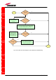
As you switch on the system, carefully refer to the “TILx-HLW start-up”
section.
TILx-
-
HLW
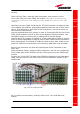
Fig. 5.39: TILx-HLW slave side
UL/DL optical
cable
Optical
jumper