
User Manual

200
User Manual
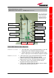
TDTX 500 transmitter:
TSRX 3xx/8 receiver:
TDTX500 transmitter:
TSRX 3xx/8 receiver
Warnings (to be read before the TILx-HLW
installation)
Dealing with optical output ports
• The TDTX modules (both on master and on slave side) contain
semiconductor lasers. Invisible laser beams may be emitted from the
TILx-
-
HLW
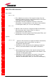
Led
colour
Meaning
Red
Optical power failure, wavelength out of
range, power supply failure
Green Power supply OK
Led
colour
Meaning
Red
Power supply failure, modem failure, RF UL
and DL failure, AGC compensation failure
Green Power supply OK
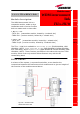
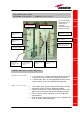
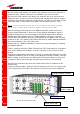
¾ 1 input port(1550 in), to be connected directly to
the optical output port of the slave-side TDTX500
transmitter
¾ 1 WDM TRX port (1310/1550nm), to be connected
to the TMRX500 module on the master side
¾ 1 output port (1550 out), to be connected directly to
the optical input port of the slave-side TSRX 3xx/8
receiver
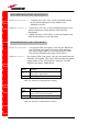
Two control LEDs (one green, one red) are placed on the
TDTX300 front panel. The green LED describes the power
supply status of the TDTX module, while the red LED
describes the major TDTX failure.
Two control LEDs (one green, one red) are placed on
the TSRX3xx/8 front panel. The green LED describes
the power supply status of the TDTX module, while the
red LED describes the major TSRX failure.
WDM I-link Slave-side: Optical ports
WDM I-link Slave-side: LED Alarms
Table 5.23:
Summary of
TSRX3xx/8 LEDs
meaning
Table 5.22:
Summary of
TDTX500 LEDs
meaning