
User Manual


120
User Manual
As highlighted in the previous table, this connector provides:
• 4 opto-isolated input ports which can be used to reveal any failure
condition on external equipment. The default status of these input
ports can be defined through the supervision system. After that, any
change from default status will be revealed as a failure signal.
• a summary of major and minor alarms related to failures detected not
only on the TPRN sub-rack, but also on any active modules hosted by
the TPRN itself.
• 2 relay output ports, which be can used to drive any external device
connected to subD-15 pins adapter. By using the supervision system
each of these output ports can set up on “open” or “close” conditions.
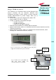
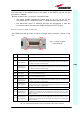
A more detailed description of the meaning and functionality of each pin are
reported in table 8. The pins are numbered from left to right, and from top to
bottom (refer to fig. 18).
Note
: The TPRN sub-rack uses I2Cbus standard protocol to collect status and
alarm information from hosted modules. Thanks to that, the alarm summaries
(provided through pins 5-6 and 7-8) report major and minor failures related
not only to TPRN sub-rack but also to any hosted module.
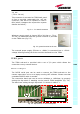
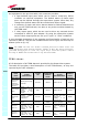
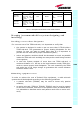
TPRN alarms
A full description of all TPRN alarms is provided by the Supervision system.
The table 4.8 provides a brief description of the TPRN alarms, as they are
reported by the LMT software o
ALARM
CODE
(TSUN
description)
ALARM
DESCRIPTION
ACTIVE
LED
SUPERVISION
PRIORITY
LEVEL
ACTION
RECOMMENDED
RELÉ
PRIORITY
LEVEL
(subrack)
Redundant
supply active
(only for
redundant
power supply
versions)
Backup power supply
activated
YELLOW MAJOR Return the unit MINOR
Power Supply
alarm
There is a
degradation on the
power supply
provided to the
boards
RED MAJOR Return the unit MAJOR
I2CBUS bus
error
Internal I2CBUS
communication
malfunction
YELLOW CRITICAL
Check if the fault is
on the unit (see
supervision
system). If not
return the unit
MINOR
Temperature
alarm
Over-temperature
alarm
YELLOW MINOR
Check ventilation
and environment
MINOR
Aux input
alarm nr0
The device
connected to the
input alarm port 0
caused an alarm
condition
RED CRITICAL
Check the status of
the connected
device
-
Aux input
alarm nr1
The device
connected to the
input alarm port 1
caused an alarm
RED MAJOR
Check the status of
the connected
device
-
TPRN