
User Manual

184
User Manual
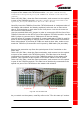
On the master-side station, the i-link modules are to be housed into 2
adjiacent slots, chosen among the 12 available ones in the subrack.
On the slave-side subrack, the i-link modules are to be housed into 4
adjiacent slots: moreover, due to the particular cabling they require, these 4
adjiacent slots should be placed in mid-subrack, so that no more than 4 TFLN
local units stay on each side of the i-link modules (as shown in fig. 5.33).
Note
: If the i-link modules are to be installed in an already working Master
Unit, switch off the sub-racks before inserting the modules.
Before inserting the boards into the TPRNx4 subracks, make sure to set
proper RS485 addresses. A basic rule of the Britecell installation is that 2
subracks belonging to the same Master Unit should always have different
RS485 addresses (please refer to “TPRN Installation” section): since the
interconnect-link basically provides an extension of the Master Unit bus, any
subrack on the i-link master-side should also have a RS485 address different
from any subrack on the i-link slave side.
Please refer to “TPRNx4 Installation” section for more information on setting
the RS485 address.
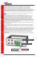
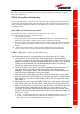
Firstly, carefully insert the TMRX200 and the TDTX300 boards in 2 adjacent
slots of the Master side subrack. Lock the 4 screws on the corners of each
boards.
Use the provided SMA-m RF jumper in order to connect the RF Out Port of the
TMRX200 module to the RF In Port of the adjacent TDTX300 module. Use the
SMB-f jumper to connect the 10.7MHz ports of the two boards. Fix these RF
jumpers to the RF ports through a proper torque wrench (not included).
Remove the protection cap from the optical ports of the 2 modules on the
master side.
Take a SC-APC fiber, clean the fibre termination, and connect it to the optical
TILx-
-HL
R
F
j
um
p
er
(
S
MA-m / SMA-m
)
RF jumper (SMB-f / SMB-f)
Fig. 5.32: TILx-HL master side
DL optical cable
UL optical
cable