
User Manual


131
MN024-08
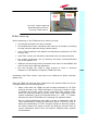
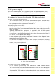
Remove the caps from TFLN optical ports
and connect the SC-APC fibre optic cables to
the ports.
UL and DL cables coming from the same
remote unit have to be connected to UL and
DL ports marked by the same number on the
TFLN front panel.
As you switch on the system, carefully refer to the TFLN Start-Up section.
Remember that remote units should be switched on before than the Master
Unit in order to follow a correct Start-Up procedure.
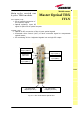
TFLN start-up
Before the Master Unit is switched on, make sure that:
• all expected modules have been inserted into the Master Unit
• the modules have been connected each other by RF jumpers, according to
what planned in the system design
• every TFLN master optical TRX has been connected to relevant remote
units
• each remote unit has been connected to its coverage antennas
• the remote supervision unit, if present, has been connected to the Master
Unit
• different Master Units are connected each other via bus RS485
After that, remember that only when all the remote units are already on, the
Master Unit itself can be turned on.
Once the Master Unit has been switched on, the TFLN behaviour at system
start-up can be summarized as per the following steps:
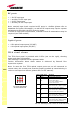
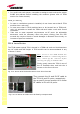
1. When Master Unit is turns on all the six LEDs upon the TFLN front panel
go on for a couple of seconds. After that, the green LED remains on
(indicating proper power supply) while the other LEDs indicate the
master optical TRX status, according to the following table.
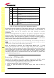
Note
: In case unused optical ports of the TFLN have not been masked
through LMT yet, corresponding LEDs will be on. If so, wait for the end
of step 3 (discovery phase) then use LMT to mask them (please refer to
relevant handbook)
2. About 10 seconds after the system has been switched on, TFLN module
begins a “discovery” phase to identify connected remote units. This
operation is necessary to collect all the information to be provided to
the supervision system.
TFLN
Fig. 5.14: Take off the caps and connect the fiber optics cables properl
y