
User Manual

228
User Manual
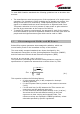
(please note that, if regulations only define the maximum electrical field
strength and the maximum magnetic field strength, the allowed power
density can be obtained as: S= E
2
/377= B
2
·377, where 377 is the
characteristics impedance of the empty space).
Example 1. Let’s suppose to use a High Power TFAH20 to distribute CDMA
signals through a directional antenna, feeded by a 2-metre length RG223
cable (no splitters used). Let’s suppose the antenna gain is 7 dB.
Let’s assume, moreover, that the maximum allowed power density we have to
comply with is: S = 10 W m
-2
(typical ICNIRP reference level for general public exposure to time-varying
electric and magnetic fields).
By reading the Britecell bulletin, we know that the output power P at the
TFAH20 antenna port is 37 dBm (=5.012 W). By reading the cable specs, we
get that RG223 cable losses can be estimated as 0.55 dB/m. Total losses
between the TFAH20 output port and the antenna input port can therefore be
estimated as follows:
L = 0.55 (dB/m) x 2 (m) = 1.1 dB
By replacing the above values of G, L, P, S parameters inside the relation 6.1,
we therefore get the the following minimum safety distance from the antenna:
r
min
= { 10 · exp [ (7 - 1.1) / 10 ] · 5.012} / (4·π·10) } · exp (-1/2) = 0.394 m
Example 2. Let’s suppose to use a Low Power TFAM85/19 through a
directional antenna, feeded by a 5 -metre length RG223 cable with a 2-way
splitter. Let’s suppose that the antenna Gain is 7 dB and that our Britecell
system distributes one Cellular800 carrier and one PCS 1900.
Let’s assume that the maximum allowed power density we have to comply
with is: S = 50 W·m
2
(typical ICNIRP reference level for occupational exposure to time-varying
electric and magnetic fields)
By reading the Britecell bulletin, we know that the output power per carrier at
the TFAM antenna port is 21 dBm (=0.126 W) for the Cellular 850 MHz
frequency band, and 20 dBm (0.1 W) in the PCS 1900 MHz frequency band.
The total output power at the antenna port is therefore P = 0.126 + 0.1 =
0.226 W.
Let’s assume that the splitter insertion losses are 3.5 dB. By reading the cable
specs, we get that RG223 cable losses can be estimated as 0.55 dB/m. Total
losses between the TFAM85/19 output port and antenna input port can
therefore be estimated as follows:
L = 0.55 (dB/m) x 5 (m) + 3.5 = 5.25 dB
By replacing the above values of G, L, P, S parameters inside the relation 6.1,
we therefore get the the following minimum safety distances from the
antenna: