5.
5.1.
Module name: Major TPRN features Subrack The TPRNx4 is a 19”subrack where all the Britecell Plus plug-in modules can be inserted. Britecell Plus equipment provides a wide variety of these sub-rack models differentiated by power supply.
TPRN models A brief description of all the available TPRN sub-racks is reported hereinafter. Passive sub-rack (TPRN04) • TPRN04 is a passive sub-rack. It does not provide power supply to any inserted module, and therefore it is designed to host passive modules only. It can be useful in a multi-sub-rack system, in case the customer decides to put all the active modules in an active sub-rack, to be chosen among the following ones.
-48 Vdc (-72 to -36 Vdc) This connector is mounted on TPRN back panel. A fuse is provided underneath the –48 Vdc connector, and has to be replaced in case it fails (when it happens the supervision system detects the failure). black terminal: 0V blue terminal:-72 to -36Vdc Fuse Fig. 5.4: -72÷-36Vdc connector Whatever power supply is chosen (85 to 264 Vac or -72 to 36 Vdc) an additional external ground terminal is provided on the TPRN rear (fig. 5.5). Fig. 5.
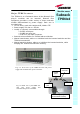
Baud rate [bps] 9600 19200 Dip-switch 5 OFF ON Table 5.1: Setting RS232 baud rate through dip-switch 5 Whichever baud rate you choose through dip-switch 5, remember that: • the same RS232 connection speed must be set up on the remote supervision unit • the baud rate which is selected through the dip-switch 5 sets the connection speed for both the RS232 port and the RS485 port as the TPRN uses both ports with the same rate.
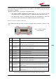
The baud rate of the RS485 ports is the same of the RS232 port as per the dip-switch 5 setting. Whichever baud rate you choose, remember that: • the same RS485 connection speed has to be set up on all the connected device (TPRN sub-racks or TSUN remote supervision unit); • the baud-rate which is selected through the dip-switch 5 sets the connection speed for both the RS485 port and the RS232 port. Sub-D 15 poles male connector The TPRN sub-rack provides a sub-D 15 poles male connector, shown in fig. 5.
As highlighted in the previous table, this connector provides: • 4 opto-isolated input ports which can be used to reveal any failure condition on external equipment. The default status of these input ports can be defined through the supervision system. After that, any change from default status will be revealed as a failure signal. • a summary of major and minor alarms related to failures detected not only on the TPRN sub-rack, but also on any active modules hosted by the TPRN itself.
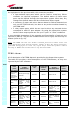
Aux input alarm nr2 Aux input alarm nr3 condition The device connected to the input alarm port 2 caused an alarm condition The device connected to the input alarm port 3 caused an alarm condition RED MINOR Check the status of the connected device - RED WARNING Check the status of the connected device - Tab. 5.
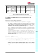
Setting the dip-switches in a multi sub-rack system If you are installing a multi-sub-rack system, remember to assign each subrack an exclusive binary address, by properly setting dip-switches 1,2,3,4 on the interior TPRN backplane (see fig. 5.6 and Tab.5.2). Dip-switch 5 has to be set on each TPRN sub-rack in order to fix the baud rate for RS485 and RS232 port.
Power supply Ground terminal Fig. 5.
• Note: in case discovery doesn’t start automatically, check through the LMT or the remote supervision whether it has been disabled (refer to LMT or remote supervision system manuals for further information). O nce the discovery has finished, the general alarm (i.e. the LED “┌┘”) on each TFLN panel stops blinking and switches OFF (provided that the TFLN master optical TRX is not affected by a general failure).
MN024-08 125
5.2.
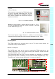
Main tasks carried out by the TFLN module Module name: Master Optical TRX TFLN Downlink (DL): ¾ RF-to-optical conversion of the input RF signal ¾ Optical splitting: input RF signal is split onto 4 optical outputs Uplink (UL): ¾ Optical-to-RF conversion of the 4 input optical signals ¾ Automatic Gain Control (AGC) of each converted signal to compensate optical losses; ¾ RF combining of the 4 adjusted signals into a single RF output UL RF Auxiliary Output (SMB-m) Status and Alarm LED DL RF Auxiliary Inpu
RF ports • • • • 1 1 1 1 DL RF input port auxiliary DL RF input port UL RF output port auxiliary UL RF output port Note: nominal input levels required at RF ports is +10dBm (please refer to datasheet for further information), as well as RF outputs may require a power adjustment to fill within the BTS receiving range. In order to fulfil these requirements, external UL and DL attenuations may be required (see TBSI module).
TFLN power supply Each TFLN master optical TRX is supplied by the sub-rack back-plane (12V). The power consumption of each TFLN master optical TRX is 12W. Warnings (to be read before the TFLN installation) Dealing with optical output ports • The TFLN master optical TRX contains semiconductor lasers. Invisible laser beams may be emitted from the optical output ports. Do not look towards the optical ports while equipment is switched on.
• In a multi-sub-rack system, remember to assign to each sub-rack a proper RS485 bus address before installing the modules (please refer to TPRN section for further details). TFLN positioning • • • In case no ventilation system is installed, do not insert more than 8 TFLN modules into a sub-rack. In case more than 8 TFLN modules have to be housed into a TPRN subrack, it’s advisable to install the TPRN sub-rack inside a rack with forced ventilation. Take care to meet expected requirements on RF ports.
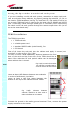
Remove the caps from TFLN optical ports and connect the SC-APC fibre optic cables to the ports. UL and DL cables coming from the same remote unit have to be connected to UL and DL ports marked by the same number on the TFLN front panel. Fig. 5.14: Take off the caps and connect the fiber optics cables properly As you switch on the system, carefully refer to the TFLN Start-Up section. Remember that remote units should be switched on before than the Master Unit in order to follow a correct Start-Up procedure.
Label LED colour Status = Green ┌┘ Red 1 Red ON (power supply is on) OFF (no major failure affects TFLN operations) OFF (no major failure affects corresponding remote connection) OFF (no major failure affects corresponding remote connection) OFF (no major failure affects corresponding remote connection) OFF (no major failure affects corresponding remote connection) 2 3 4 Red Red Red unit or UL unit or UL unit or UL unit or UL Table 5.
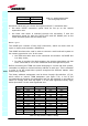
TFLN troubleshooting In case a TFLN master optical TRX has any problem, this will be easily revealed through LEDs on its front panels otherwise troubleshooting can be carried out through LMT or supervision system. LEDs on TFLN front panel detect not only failures of the TFLN board itself but they also reveals malfunctions located on related remote units.
The previous table reports a brief description of the TFLN alarms, together with a reference to the corresponding alerted LEDs. As the table shows, LEDs on the TFLN front panel signal all high priority alarms while minor alarms, which detect critical situations which should be checked and tested in order to avoid future possible system faults, are only revealed by LMT or supervision system. Each TFLN is provided with an AGC system which compensates optical losses <3 dB.
to the TFAx side, disconnect the optical SC-APC connector from TFAx UL port and measure the input power PIN(UL) coming out of the TFAx UL port. 5. Calculate the UL fibre attenuation AUL as: AUL [dB] = PIN(UL) – POUT(UL) a. If AUL > 4dB, the fibre optic cable has some problems or cable path is too long. Replace it. b. If AUL < 4dB, then TFAx remote unit should be faulty.
No Is any red LED ON upon the TFLN? start Yes Which red LED is ON? Replace the faulty TFLN 1, 2, 3 or 4 Clean corresponding SC-APC optical adapter and connector Is red LED upon TFLN still ON? No Yes Go to corresponding remote unit side Is red LED upon remote unit ON? No Yes UL optical cables or optical connections are supposed to have some problems. Refer to fibre optic UL troubleshooting (fig. 5.
Is there any small radius of curvature of the fibre? start Rearrange the optical path in order to avoid sharp bends. If necessary replace the optical cable with a longer one. Yes No Yes Are SC-APC connectors properly installed at both fibre ends? Is the red LED upon TFLN still ON? No Fix SC-APC connectors properly to adapters. No Yes Yes Yes Disconnect the optical SC-APC connector from TFLN UL port.
5.3.
Description: The TLCN2, a bidirectional 2-way splitter/combiner, provides two identical combining sections for UL and DL which can be used: ¾ to combine 2 RF signals into a common RF output ¾ to split an RF input into 2 RF output signals It is a passive wideband module.
TLCN2 insertion loss The TLCN2 insertion loss varies slightly with the frequency bands, as shown in table 5.7. When designing the system, remember to take into account the insertion loss of the TLCN2 if present. TLCN2 insertion loss 700-1400MHz 1400-2200MHz 2200-2500MHz 3.7 ± 0.4dB 4.1 ± 0.5dB 4.6 ± 0.4dB Table 5.
MN024-08 141
5.4.
Module name: Description: The TLCN4, bidirectional 4-way splitter/combiner, provides two identical combining sections for UL and DL which can be used to: ¾ combine 4 RF signals into a common RF output ¾ split an RF input into 4 RF output signals It is a passive wideband module.
The TLCN4 insertion losses vary slightly with the frequency bands, as shown in table 5.8. When designing the system, remember to take into account the insertion loss of the TLCN4. TLCN4 insertion loss 700-1400MHz 1400-2200MHz 2200-2500MHz 7.4 ± 0.4dB 8.0 ± 0.5dB 8.4 ± 0.4dB Table 5.
MN024-08 145
5.5.
Description: Module name: RF dual-band coupler TLDN The TLDN is a passive RF dual band coupler designed to distribute signal within the master unit when coming from different bands. Main operations carried out are: ¾ in downlink it combines a low band RF signal (800MHz to 1000MHz) and a high band RF signal (1700MHz to 2200MHz) into a common RF path ¾ in uplink it filters the composite signal into a low-band (800MHz to 1000MHz) and a high-band (1700MHz to 2200MHz) one. It is a passive module.
¾ TLDN filters the UL input coming from a TFLN master optical TRX into 2 UL outputs entering 2 different donor sources (carrying different services) TLDN insertion loss TLDN insertion loss = 1.0 ± 0.5dB. When designing the system, remember to take into account the insertion loss of the TLDN. Warnings The overall input power must not exceed +27dBm TLDN Installation Since the TLDN module doesn’t require any power supply it can be housed either in an active or a passive TPRN sub-rack. 1.
MN024-08 149
5.6.
Module name: Description: RF tri-band coupler TLTN The TLTN is a passive RF tri band coupler designed to distribute signal within the master unit when coming from different bands. Main operations carried out are: ¾ in downlink it combines a 800MHz to 1000MHz, a 1700MHz to 2000MHz signal and a 2000MHz to 2200MHz signal into a single RF path ¾ in uplink it filters a composite signal into a 800MHz to 1000MHz, a 1700MHz to 2000MHz signal and a 2000MHz to 2200MHz one. It is a passive module.
¾ TLTN combines the DL inputs coming from 3 different donor sources (carrying different services) into an output signal entering the TFLN master optical TRX ¾ TLTN filters the UL input coming from the TFLN master optical TRX into 3 UL outputs entering 3 different donor sources (carrying different services) TLTN insertion loss TLTN insertion loss = 3.0 ± 0.5dB When designing the system, remember to take into account the insertion loss of the TLTN.
MN024-08 153
5.7.
Description: Module name: RF tri-band coupler TDPX TDPX is a frequency dependent duplexer that combines downlink and uplink signals while maintaining isolation and stability. This board has been designed to support where the source is duplexed.
Warnings The overall input power must not exceed +30dBm. As the module is band dependent be sure to choose the right single band version. TDPX Installation Since the TDPX module doesn’t require any power supply it can be housed either in an active or a passive TPRN sub-rack. 1. Unpack the kit which include 1 TDPX 2 RF jumpers (SMA-m), 2 x 35cm 2. Carefully insert the TDPX module in any of the TPRN sub-rack slots and lock the 4 screws on the front corners. 3.
MN024-08 157
5.8.
Module name: Description Base station interface TBSI The TBSI module adjusts the signal level between the donor source and the Britecell Plus system.
When designing the system, remember to take into account the insertion loss of the TBSI. Warnings The overall input power must not exceed +30dBm TBSI Installation Since the TBSI module doesn’t require any power supply it can be housed either in an active or a passive TPRN sub-rack. 1. Unpack the kit which include 1 TBSI 2 RF jumpers (SMA-m), 1 x 35cm, 1 x 45cm 2. Carefully insert the TBSI module in any of the TPRN sub-rack slots and lock the 4 screws on the front corners. 3.
MN024-08 161
5.9.
Module name: Description Power Limiter The TMPx-10 power limiter monitors the downlink input power and attenuates it by 10dB above a predetermined set point. The threshold is programmable through the supervision system. TMPx-10 power limiter is available in two versions, one suitable for GSM DL (800 to 1000MHz or 1800 to 2000MHz) and the other for UMTS 2100MHz DL.
TMP power supply Each TMPx-10 power limiter is supplied by the sub-rack back-plane (+12V). The power consumption of each TMPx-10 is 2W max TMP insertion loss TMP insertion loss < 1.7dB. When designing the system, remember to take into account the insertion loss of the TMP. Warnings The overall input power must not exceed +35dBm. Inserting or removing TMP modules • Do not remove or insert any TMP module into TPRN sub-rack before having switched off main power supply.
Removing a TMP module Switch off the Master Unit power supply and remove RF jumpers. Then • unscrew the 4 screws and slowly remove the card. • put the removed TMP card in its safety box. • switch on again the Master Unit power supply and refer to TFLN Start-up section. TMP troubleshooting In case a TMP power limiter has any problem, this will be easily revealed through LEDs on its front panel otherwise troubleshooting can be carried out through LMT or supervision system.
a. If there isn’t any RF signal at the input, check if the RF cable is connected at the input port. If it’s connected check the power coming out from the donor source. b. Otherwise the temperature range is not within the specified range, change the temperature range or provide proper air flow. Is red LED ON upon the TMP? start Yes Yes No No Is green No LED OFF upon the TMP? Problem on power supply Is yellow LED ON upon the TMP? RF level @ input port has exceeded the threshold. Check the RF signal.
MN024-08 167
5.10.
Module name: Description Wi-Fi Local Interface TWLI Britecell Plus system allows distributing WLAN service (802.11b and g) through the auxiliary channel while concentrating all the Access Points together with the central equipment. The TWLI module allows connecting up to 3 Access Points to one TFLN master optical TRX and setting up to 4dB attenuation, if needed, on the DL path.
Warnings The overall input power must not exceed +19dBm The TWLI modules must be handled with care, in order to avoid damage to electrostatic sensitive devices. TWLI Inserting or removing TWLI modules • • • • Do not remove or insert any TWLI module into TPRN sub-rack before having switched off main power supply. The TWLI modules must be handled with care, in order to avoid damage to electrostatic sensitive devices.
MN024-08 171
5.11.
5.11.1. Introduction Module name: Interconnect link TILx-HL TILx-HLW the interconnect link is a set of modules which allows to expand the system by connecting a second Britecell Plus subrack station to the main one, at a distance of up to 20 km. By using more interconnect links at the main station, more Britecell Plus stations could be connected to the main one, in a star configuration. Each interconnect link (i-link) is made up by a master-side and by a slaveside.
TFAx TFAx TFLN GSM 900 BTS TFAx Fixed Atten TFAx TFAx TILx (intro) GSM 1800 BTS UMTS BTS Fixe d Fixed Atten BTS INTERFACING SECTION + SPLITTING COMBINING SECTION TFLN TFAx TFAx TFAx TMRX TDTX TFAx TFAx TFLN TFAx TDTX TSRX TFAx TFAx TFAx TFLN TFAx TFAx Fig. 5.
TFAx TFAx TFLN GSM 900 BTS GSM 1800 BTS Fixed Atten Fixe d TFAx TFAx BTS INTERFACING SECTION + SPLITTING COMBINING SECTION TFAx TFLN TFAx TILx (intro) TFAx TFAx TMRX TDTX TFAx UMTS BTS Fixed Atten TFAx TFLN TFAx TDTX TSRX TFAx TFAx TFAx TFLN TFAx TFAx Fig. 5.
TILx (intro) 176 User Manual
Module name: 5.11.2.
Main TILx-HL functions: Downlink: Master side: • RF-to-Optical conversion of the signal coming from the splitting/combining section, and transmission to the slave i-link modules via fiberoptics cable; • Modulation and RF-to-Optical conversion of the bus information, and transmission to the slave i-link modules via fiberoptics cable (on 1310 nm wavelength); TILx-HL Slave side • Optical-to-RF conversion of signal and alarm information, with Automatic Gain Control (AGC) in order to compensate the optical los
TILx-HL Master Side: TDTX300 transmitter + TMRX200 receiver Fig.5.
TILx – HL Master-side: Optical ports T DTX300 transmitter: ¾ 1 Optical output port, to be connected directly to the optical input port of the slave-side TSRX2xx/8 receiver TMRX200 receiver: ¾ 1 Optical input port, to be connected directly to the optical output port of the slave-side TDTX300 transmitter TILx-HL TILx – HL Master-side: LED Alarms TDTX300 transmitter: TMRX200 receiver: Led colour Red Green Two control LEDs (one green, one red) are placed on the TDTX300 front panel.
TILx - HL Slave-Side: TDTX300 transmitter + TSRX2xx/8 receiver TSRX TDTX300 Fig.5.
TILx -HL Slave-side: Optical ports TDTX 300 transmitter: ¾ 1 Optical output port, to be connected directly to the optical input port of the master-side TMRX200 receiver TSRX2xx/8 receiver: ¾ 1 Optical input port, to be connected directly to the optical output port of the master-side TDTX300 transmitter TILx-HL TILx – HL Slave-side: LED Alarms TDTX300 transmitter: Two control LEDs (one green, one red) are placed on the TDTX300 front panel.
Warnings (to be read before the TILx – HL installation) Dealing with optical output ports • The TDTX modules (both on master and on slave side) contain semiconductor lasers. Invisible laser beams may be emitted from the optical output ports. Do not look towards the optical ports while equipment is switched on. Handling optical connections • When inserting an optical connector, take care to handle it so smoothly that the optical fibre is not damaged. Optical fibres have to be single-mode (SM) 9.5/125µm.
On the master-side station, the i-link modules are to be housed into 2 adjiacent slots, chosen among the 12 available ones in the subrack. On the slave-side subrack, the i-link modules are to be housed into 4 adjiacent slots: moreover, due to the particular cabling they require, these 4 adjiacent slots should be placed in mid-subrack, so that no more than 4 TFLN local units stay on each side of the i-link modules (as shown in fig. 5.33).
out port of the master-side TDTX300 module. (This fiber shall be directly connected to the optical in port of the TSRX2xx/8 module on the slave-side subrack) Take a SC-APC fiber, clean the fibre termination, and connect it to the optical in port of the TMRX200 module (This fiber shall be directly connected to the optical out port of the TDTX300 on the slave-side subrack) Carefully insert the TSRX2xx/8 and the TDTX300 boards in 4 adjacent slots of the Master side subrack.
Removing a TILx - HL module To remove an i-link module, firstly switch off the TPRNx4 subrack which houses the module. Remove the fibers and the RF jumpers connected to the i-link module which is going to be removed. Insert the caps on the optical ports which has just been disconnected. Unscrew the 4 screws at the corners of the i-link module which is going to removed, and slowly remove the card.
whose duration depends on the system complexity and which can last at max. 4min, the TFLN LEDs ┌┘ blink. Do not connect/disconnect any cable or any piece of equipment during the discovery phase! This may result in failing the identification of some equipment. Note: in case discovery doesn’t start automatically, check through the LMT or the remote supervision whether it has been disabled (refer to LMT or remote supervision system manuals for further information).
TDTX 300 (master side or slave side) ALARM CODE (TSUN description) TILx-HL ALARM DESCRIPTION ACTIVE LED SUPERVISION PRIORITY LEVEL ACTION RECOMMENDED RELÉ PRIORITY LEVEL (subrack) RED MAJOR Return the unit MAJOR MINOR Vcc alarm There is a degradation on the power supply provided by the backplane Optical power <1dB The received optical power experiences a degradation which is near to the AGC working threshold (but it can still compensate losses) NONE MINOR Check the optical loss / AGC statu
TMRX 200 ALARM CODE (TSUN description) ALARM DESCRIPTION ACTIVE LED SUPERVISION PRIORITY LEVEL ACTION RECOMMENDED RELÉ PRIORITY LEVEL (subrack) RED MAJOR Return the unit MAJOR WARNING Check the optical loss / AGC status on the TSRX or TMRX module at the other side of the imterconnect link MINOR MAJOR Return the unit MAJOR MINOR Power supply alarm There is a degradation in power supply distribution RX1 AGC out of range The received optical power experiences a degradation which is near to
TSRX 2xx/8 ALARM CODE (TSUN description) ALARM DESCRIPTION Power supply alarm There is a degradation in power supply distribution RX1 AGC out of range The received optical power experiences a degradation which is near to the AGC working threshold (but it can still compensate losses) RX1 Optical power fail The transmitted optical power experiences a degradation which can no more be compensated by the AGC TILx-HL SUPERVISION PRIORITY LEVEL ACTION RECOMMENDED RELÉ PRIORITY LEVEL (subrack) MAJOR Re
RF jumper. If the RF connection proves to be ok and the red LED keep on switching on, please contact the manufacturer. TMRX-200 module troubleshooting Ordinary troubleshooting procedures which can be carried out on TMRX-200 module first involve a check of the optical adapter status and of the fiberoptics cable. If the alarm status still persists, a reboot of both the TMRX-200 module and of the TSRX-2xx/8 module can be performed so as to re-inizialize the link.
TSRX-2xx/8 module troubleshooting Ordinary troubleshooting procedures which can be carried out on TMRX-200 module first involve a check of the optical adapters status and of the fiberoptics cables. If the alarm status still persists, a reboot of both the TMRX-200 module and of the TSRX-2xx/8 module can be performed so as to verify if the problem depends on a failed modem connectivity. Quick TSRX-2xx/8 troubleshooting procedure TILx-HL (The following procedure is summarized by the flow-chart in fig. 5.
Is there any point where the fibre experiences a small radius of curvature? start Yes Rearrange the optical path to avoid sharp bends. If necessary replace the optical cable with a longer one. No Is red LED upon TMRX/TSRX still ON? Yes Are SC-APC connectors properly installed at both fibre ends? No No TILx-HL Fix better SCAPC connectors Yes Yes Disconnect the fiber optic cable and clean it at both ends.
Is the red LED ON upon the TSRX 2xx/8? start No Yes Clean the SC-APC optical adapter and connector Is red LED upon TSRX 2xx/8 still ON? No Yes TILx-HL Optical cable or optical connections may have some problems. Refer to TMRX/TSRX fiberoptic troubleshooting (fig. 5.
Module name: 5.11.3.
Main TILx-HLW functions: Downlink: Master side: • RF-to-Optical conversion of the signal coming from the splitting/combining section, and transmission to the slave i-link modules via fiberoptics cable; • Modulation and RF-to-Optical conversion of the bus information, and transmission to the slave i-link modules via fiberoptics cable (on 1310 nm wavelength); Slave side TILxHLW • Optical-to-RF conversion of signal and alarm information, with Automatic Gain Control (AGC) in order to compensate the optical lo
TILx-HLW Master Side: TDTX300 transmitter + TMRX500 receiver Fig. 5.
TILx-HLW Master-side: Optical ports TDTX300 transmitter: ¾ 1 output port (1310 out), to be connected directly to the optical input port of the master-side TMRX500 receiver TMRX500 receiver: ¾ 1 input port (1310 in), to be connected directly to the optical output port of the master-side TDTX300 transmitter ¾ 1 WDM TRX port (1310/1550), to be connected to the TSRX3xx/8 module on the slave side TILx-HLW Master-side: LED Alarms TILxHLW TDTX300 transmitter: Two control LEDs (one green, one red) are placed on th
TILx-HLW Slave-Side: TDTX500 transmitter + TSRX3xx/8 receiver TDTX 500 TSRX 3xx/8 RF port connected to TSRX3xx/8 slave (SMA-f) RF Rx port from TDTX500 slave (SMA-f) RF Rx port from TDTX500 slave (SMB-m) RF port connected to TSRX3xx/8 slave (SMB-m) GREEN LED: power on RED LED:major alarm GREEN LED: pwr on RED LED:major alarm Optical port to be connected to TMRX-500 master (SC-APC) Fig.5.
WDM I-link Slave-side: Optical ports TDTX 500 transmitter: TSRX 3xx/8 receiver: TILxHLW ¾ 1 output port (1550 out), to be connected directly to the optical input port of the slave-side TSRX 3xx/8 receiver ¾ 1 input port(1550 in), to be connected directly to the optical output port of the slave-side TDTX500 transmitter ¾ 1 WDM TRX port (1310/1550nm), to be connected to the TMRX500 module on the master side WDM I-link Slave-side: LED Alarms TDTX500 transmitter: Two control LEDs (one green, one red) are pl
optical output ports. Do not look towards the optical ports while equipment is switched on. • Handling optical connections • When inserting an optical connector, take care to handle it so smoothly that the optical fibre is not damaged. Optical fibres have to be single-mode (SM) 9.5/125µm. • Typically, Britecell Plus equipment is provided with SC-APC optical connectors. Inserting any other connector will result in severe damages.
On the master-side station, the WDM i-link modules are to be housed into 2 adjiacent slots, chosen among the 12 available ones in the subrack. On the slave-side subrack, the WDM i-link modules are to be housed into 4 adjiacent slots: moreover, due to the particular cabling they require, these 4 adjiacent slots should be placed in mid-subrack, so that no more than 4 TFLN local units stay on each side of the WDM i-link modules (see fig. 5.39).
module. Take a SC-APC fiber, clean the fibre termination, and connect it to the 1310/1550 TRX port of the TMRX 500 module (This fiber shall be directly connected to the 1310/1550 TRX port of the TSRX 3xx/8 on the slave-side subrack) Carefully insert the TSRX-3xx/8 and the TDTX-500 boards in 4 adjacent slots of the Master side subrack. As already explained, take care not to have more than 4 TFLN modules on each side of the i-link pieces. Lock the 4 screws on the corners of each boards.
Removing a TILx-HLW module To remove a TILx-HLW module, firstly switch off the TPRNx4 subrack which houses the module. Remove the fibers and the RF jumpers connected to the WDM i-link module which is going to be removed. Insert the caps on the optical ports which has just been disconnected. Unscrew the 4 screws at the corners of the WDM i-link module which is going to removed, and slowly remove the card.
cable or any piece of equipment during the discovery phase! This may result in failing the identification of some equipment. Note: in case discovery doesn’t start automatically, check through the LMT or the remote supervision whether it has been disabled (refer to LMT or remote supervision system manuals for further information).
TDTX300 (master side) ALARM CODE (TSUN description) Vcc alarm TILxHLW ALARM DESCRIPTION There is a degradation on the power supply provided by the backplane ACTIVE LED SUPERVISION PRIORITY LEVEL ACTION RECOMMENDED RELÉ PRIORITY LEVEL (subrack) RED MAJOR Return the unit MAJOR MINOR Optical Power < 1dB The received optical power experiences a degradation which is near to the AGC working threshold (but it can still compensate losses) NONE MINOR Check the optical loss / AGC status on the TSRX or
TMRX500 (master side) ALARM CODE (TSUN description) Power supply alarm AGC out of range Optical power fail ALARM DESCRIPTION There is a degradation in power supply distribution The received optical power experiences a degradation which is near to the AGC working threshold (but it can still compensate losses) The transmitted optical power experiences a degradation which can no more be compensated by the AGC SUPERVISION PRIORITY LEVEL ACTION RECOMMENDED RELÉ PRIORITY LEVEL (subrack) MAJOR Return the u
TDTX500 (slave side) ALARM CODE (TSUN description) TILxHLW ALARM DESCRIPTION ACTIVE LED SUPERVISION PRIORITY LEVEL ACTION RECOMMENDED RELÉ PRIORITY LEVEL (subrack) RED MAJOR Return the unit MAJOR MINOR Vcc alarm There is a degradation on the power supply provided by the backplane Optical power < 1 dB The received optical power experiences a degradation which is near to the AGC working threshold (but it can still compensate losses) NONE MINOR Check the optical loss / AGC status on the TSRX
TSRX3xx/8 (slave side) ALARM CODE (TSUN description) ALARM DESCRIPTION Power supply alarm There is a degradation in power supply distribution AGC out of range The received optical power experiences a degradation which is near to the AGC working threshold (but it can still compensate losses) NONE WARNING Optical power fail The transmitted optical power experiences a degradation which can no more be compensated by the AGC RED MAJOR ACTIVE LED RED SUPERVISION PRIORITY LEVEL MAJOR ACTION RECOMMEN
TILxHLW As shown by these tables, the LEDs show only the alarms concerning the board where they are housed: so, a red LED which is switched on at TSRX front side reveals an alarm affecting the TSRX module itself (it does not deals with the alarms affecting the other module of the i-link slave-side, which is an TDTX300, and whose alarms will be detected by its own LEDs). Moreover, these tables show that the LEDs reveals only major alarms, whereas the minor alarms (i.e.
TMRX/TSRX fibre optic troubleshooting (The following procedure is summarized by the flow-chart in fig. 5.40b) 1. Check if there is any point where fibre experiences a short radius of curvature. In this case, rearrange the optical path in order to avoid sharp bends (if necessary, replace the optical cable with a longer one). If TMRX (TSRX) red LED switches off, troubleshooting has been successfully carried out. Otherwise, follow next steps. 2.
Is the red LED ON upon the TMRX 500? start No Yes Clean the SC-APC optical adapter and connector Is red LED upon TMRX 500 still ON? No Yes Optical cable, optical jumper or optical connections may have some problems. Refer to TMRX/TSRX fiberoptic troubleshooting (fig. 5.
Is there any point where the fibre experiences a small radius of curvature? start Yes Rearrange the optical path to avoid sharp bends. If necessary replace the optical cable with a longer one. No Is red LED upon TMRX/TSRX still ON? Yes Are SC-APC connectors properly installed at both fibre ends? No No Fix better SCAPC connectors TILxHLW Yes Yes Disconnect the fiber optic cable and clean it at both ends.
Is the red LED ON upon the TSRX 2xx/8? start No Yes Clean the SC-APC optical adapter and connector Is red LED upon TSRX 2xx/8 still ON? No Yes Optical cable or optical connections may have some problems. Refer to TMRX-TSRX fiberoptic troubleshooting (fig.5.
MN024-08 215
5.11.
The TRS/TRSN is a sub-rack unit which provides remote supply to up to 24 remote units, by means of dedicated outputs with short-circuit protection switches. It is available in 2 versions. The TRSN version is able to supply 1 A per port and it can feed all remote units. The TRS version is able to supply 0.5A per port: it can feed only single and dual band TFAN remote units, as well as the TFAM20 one. The TRS/TRSN unit provides DC power supply to the remote units through standard AWG14/16 copper lines.
Fig. 5.42. Picture of 12- output TRSN subrack. Ports TRS TRSN The TRSN version (suitable to all types of remote units) is available with • 12 supply outputs • 24 supply outputs It can supply 1 A per port. The TRS version (suitable to single and dual band TFAN remote units and to TFAM20) is available with 24 supply outputs. It can supply 0.5 A per port. Power supply Both the TRS and the TRSN subracks can be feeded either by 115 Vac mains or by 230 Vac mains (50/60Hz).
The TRSN subrack is also available in passive version TRSNx-3, which can be feeded by direct current (–72 to –36 Vdc). In this case, the -48 Vdc current is conveyed to the remote units thanks to a passive distribution system (please refer to fig. 5.45b). Please read carefully the cabling instructions in order to connect the provided power cable to the poles of the -48 Vdc connector properly (see fig.5.44b). TRS TRSN (b) (a) Fig. 5.44.
Warnings • Caution: do not open the unit before disconnecting the mains. Internal assemblies can be accessed by qualified personnel only. • Do not connect supply outputs to remote units before switching off the unit or disconnecting the mains. Being a DC supply provided, a wrong connection can damage the remote unit.
If a surge or an overloading condition occur the switch automatically jump into an OFF position. TRS/TRSN behaviour at start-up • • • • • • Check if power supply voltage selector is in the correct position (115 or 230 Vac). In passive distribution version this selector is not present.
6.
6.1. Environmental Conditions This equipment is designed to be installed in indoor environments. Operating temperature: +5 to +40°C (for all the pieces of equipment, except remote units case L) -20 to +50°C (only for remote units case L) Do not install in corrosive atmosphere or in critical environmental conditions such as hazardous classified areas (1). 6.2. Installation Site Features A trained technician should carry out the installation of the master unit.
• • • • • each remote unit requires its own power and a connection to the mains can be needed; keep into consideration that each remote unit transmits RF signal and safety volume must be respected (refer to country regulations for safety volume magnitude); remote units must be mounted according to what specified in the relevant installations instructions; Weight and dimensions of case-L and case-F remote units should be carefully considered when choosing the installation site and positioning.
CAUTION: Case-F and Case-L remote units are provided with some door panels which have to be managed with care during installation or maintenance operations.. Always switch off the remote while working with the panel opened. When closing the panels, take care not to leave any tool inside the equipment, not to hurt your fingers, and not to trap clothes, bracelets, chains, or long hair. Never remove the cover from a TFAx remote unit or from a TPRN subrack when the power supply is ON. 6.4.
6.5. Safety and Precautions for Lasers The optical transmitter used in Britecell Plus contains a laser which has a power level that is not dangerous for health. However it is classified as class 1 equipment (in accordance to EN60825). It is nevertheless prudent in the installation phase to observe the following rules: • Never look directly inside the optic connector exit of the transmitters when it is switched on.
To meet RSS Canadian standards the following guidelines has to be taken into account: • • The manufacturer rated output power of the equipment is for single carrier operation. For situations in which multiple carrier signals are present, the rating would have to be reduced by 3.5dB especially when the output signal is re-radiated and can cause interference to adjacent band users. This power reduction is to be by means of input power or gain reduction and not by an attenuator at the output of the device.
(please note that, if regulations only define the maximum electrical field strength and the maximum magnetic field strength, the allowed power density can be obtained as: S= E2/377= B2·377, where 377 is the characteristics impedance of the empty space). Example 1. Let’s suppose to use a High Power TFAH20 to distribute CDMA signals through a directional antenna, feeded by a 2-metre length RG223 cable (no splitters used). Let’s suppose the antenna gain is 7 dB.
rmin = { 10 · exp [ (7 - 5.25) / 10 ] · 0.226} / (4·π·50) } · exp (-1/2) = 0.023 m Example 3. Let’s suppose to have a Low Power TFAM90/20 connected to an omnidirectional antenna through a 20-metre length ½” cable (no splitters used). Let’s suppose that the antenna Gain is 7 dB and that our Britecell system distributes two GSM900 carriers and one UMTS2100 carrier.
6.8. Warning Labels CLASS 1 laser product Fig. 6.1: Laser safety Label GROUND - Use this terminal for a safety ground connection of the equipment. Fig. 6.2: Ground Label Fig. 6.3: WEEE Identification Label When this equipment is no longer used, please do not throw it into a trush container as unsorted municipal waste. Waste electrical electronic equipment (WEEE) must be collected apart and disposed of according to the European Directives 2002/96/EC and 2003/108/EC.
7. TECHNICAL SUPPORT Andrew Corporation offers technical support by providing these 24-Hour call services: North America (toll free) to U.S.A. Telephone 1-800-255-1479 Fax 1-800-349-5444 Any Location (International) to U.S.A. Telephone + 1(708) 349-3300 Fax + 1 (708) 349-5410 Britecell Plus is developed by: Andrew Wireless Systems Srl Via Pier De Crescenzi 40 48018 Faenza, Italy Tel: +39.0546.697111 Fax: +39.0546.
Before sending any piece of equipment to the manufacturer, you must send us the following RMA request form via fax (+39 0546 682768) or via e-mail (britecell@andrew.com). RMA REQUEST FORM Company name Address Contact person Invoice number Delivery note N°. of pieces Model1 Serial Number1 Lot1 Year1 Description of the Failure/defect 1 Please refer to the serial label Upon accepting your RMA request, the manufacturer will assign you a unique RMA code.
Appendix A: System Commissioning The following flow charts want to be a quick reference for Britecell Plus® system installation and commissioning. The first flow chart (see Fig. A.1) highlights the main steps for system installation and commissioning starting from the equipment unpacking up to the check of the coverage and call quality. START UNPACK THE EQUIPMENT ARE THERE ANY BOXES LEFT? YES NO INSTALL AND CABLE MASTER UNIT INSTALL AND CABLE REMOTE UNITS (see flow chart in Fig.
The previous flow chart contains the following cross references: • the master unit installation and cabling is described in more details in the flow chart in figure A.3. It takes care of the flow of actions from the sub-rack mounting on the cabinet up to the settings and connections needed in case a remote supervision has to be considered. An example of system layout at master unit side is presented in figure A.2 for a configuration consisting in 1 sector with 4 TFLN master optical TRXs.
master unit switch on and discovery up to the system configuration through LMT Software and/or remote supervision system. For more details on how to use LMT and about TSUNx configuration and start-up refer to relevant manuals. • in case the system is not working properly, refer to the troubleshooting procedures reported into relevant sections. MOUNT THE SUBRACK INTO THE CABINET START SET THE SUBRACK BAUD RATE (THE SAME FOR ALL) (see Fig. 16 and Tab.
START ARE ALL REMOTE UNITS SWITCHED ON? NO SWITCH THEM ON Fig. A.
Appendix B: EU Guidelines for WEEE disposal All Britecell Plus products are properly labelled (please refer to fig. B.1) so as to inform the customer that no piece of equipment should be treated as unsorted municipal waste. Within the EU boundariers, any Britecell Plus equipment which is no longer used should be treated and disposed of according to European Directives 2002/96/EC and 2003/108/EC.
Alluminium (external case) Metal (RF connectors, screws, cavity filters) Plastic (optical connectors and adapters ; power connector; ) • cables, fiberoptics cables, internal circuit boards, psu, inlet • None Alluminium (external case; wall-fixing plates; pipe connection and PG 13,5 ; strain reliefs) Metal (RF connectors, screws, cavity filters) Plastic (optical connectors and adapters ; power connector; ) • cables, fiberoptics cables, internal circuit boards, psu, inlet • None TKA installation kit
TRS / TRSN • • • TSUN 6 • • TSUN 1 / TSUN 3 • Alluminium (external case) Metal (screws) Copper (Transformers model with active distributions) Alluminium (front panel) Metal (screws) Metal (screws, external case) • cables, internal circuits, circuit breakers • None • Internal circuit board • None • Internal circuit board, psu, inlet • None Table B.1.