
Install Manual


BRITECELL System Manual MN010-04 June 2003 Page 47 of 78
The company has a policy of continuous product development and improvement and we therefore
reserve the right to vary any information quoted without prior notice.
36. Introduction
This section describes the TLC splitter/combiner. The TLC is part of Britecell
system and provides a family of 2-way and 3-way RF power combiners in order to
allow several local interface modules to be connected to common UL and DL RF
paths, for interfacing to the BTS.
All units have internal pads (one per path) to achieve predefined insertion loss.
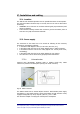
37. Part description
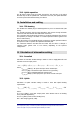
Fig. 32 TLC2502 Fig. 33 TLC2501
38. Functional description
TLC2502/3 is a two/three way splitter for downlink path and combiner for uplink
path. For insertion loss values refer to datasheets.
TLC2501 is a crossband coupler, designed to combine or split hi-band signal and
low band signal in dual band systems. Insertion loss in this case is minimal (see
datasheets).
39. Warnings
9
Maximum RF composite input power must not exceed 24 dBm.
9
SMA connectors must be screwed with a proper dynamometric key.
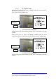
40. Installation and cabling
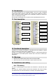
40.1. TPR housing
The TLC is a modular plug-in card, suited to be contained in a 6 HE Sub rack (TPR
family).
The 2-way TLC module interfaces with the BTS transmitter and receiver through
TFL-BSI and with TFL Local Units directly or through 3-way splitter/combiner.
Downlink RF input
Downlink RF
splitted outputs
Uplink RF
combined output
Uplink RF inputs
Downlink RF
High Band input
Downlink RF
combined output
Downlink RF
Low Band input
Uplink RF
High Band output
Uplink RF
combined input
Uplink RF
Low Band output