
Install Manual


BRITECELL System Manual MN010-04 June 2003 Page 44 of 78
The company has a policy of continuous product development and improvement and we therefore
reserve the right to vary any information quoted without prior notice.
30. Introduction
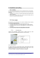
This section describes the TFL-BSI (Base Station Interface). The TFL-BSI is part of
the Britecell system and allows the operator to optimise the signal level the BTS or
repeater and the Britecell system. It includes two independent variable attenuators
(30 dB, one dB step) for uplink and downlink RF path.
A single attenuator version is available, for downlink only or uplink only operations.
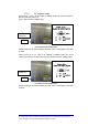
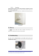
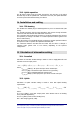
31. Part description
Fig. 31 - TFLBSI
32. Warnings
9
Maximum RF composite input power must not exceed 30 dBm.
9
SMA connectors must be screwed with a proper dynamometric key.
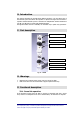
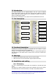
33. Functional description
33.1. Down link operation
If the RF signal coming from the BTS or repeater in downlink path has a power
level, which is not adequate to the TFL’s characteristics, an attenuator is required.
Downlink RF input (from BTS)
Downlink attenuation settings
Downlink RF output (to TFL)
Uplink RF output (to BTS)
Uplink attenuation settings
Uplink RF input (from TFL)