
Install Manual


BRITECELL System Manual MN010-04 June 2003 Page 76 of 78
The company has a policy of continuous product development and improvement and we therefore
reserve the right to vary any information quoted without prior notice.
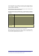
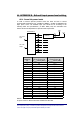
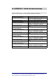
66.2. Down link power levels: remote unit + booster
NUMBER OF
CARRIERS
(N)
Max power per
carrier at TFL DL RF
input (a)
P
IN TFL
/carrier
[dBm]
Max power per
carrier at TFA RF
output (b)
P
OUT TFA
/carrier
[dBm]
Max power per
carrier at TFB RF
output (c)
P
OUT TFB
/carrier
[dBm]
1 0,0 7,0 20,0
2 -4,0 3,0 16,0
3 -6,3 0,7 13,7
4 -7,3 -0,3 12,7
5 -8,2 -1,2 11,8
6 -8,8 -1,8 11,2
7 -9,3 -2,3 10,7
8 -9,7 -2,7 10,3
9 -10,1 -3,1 9,9
10 -10,4 -3,4 9,6
11 -10,7 -3,7 9,3
12 -11,0 -4,0 9,0
14 -11,5 -4,5 8,5
16 -11,9 -4,9 8,1
18 -12,2 -5,2 7,8
20 -12,6 -5,6 7,4
22 -12,8 -5,8 7,2
26 -13,3 -6,3 6,7
30 -13,8 -6,8 6,2
34 -14,1 -7,1 5,9
40 -14,6 -7,6 5,4
NOTES:
DL power levels for Britecell 900 MHz + TFB915
DL power levels for Britecell 1800 MHz + TFB1815
The DL levels at Booster output assume that the cable connecting TFA and booster
has 1 dB loss.
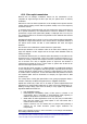
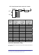
TFLxxxx4H-x
TFL DL RF
input
TFL UL RF
output
a
b
b
c
TFBxxxx
TFAxxxx