
Install Manual


BRITECELL System Manual MN010-04 June 2003 Page 75 of 78
The company has a policy of continuous product development and improvement and we therefore
reserve the right to vary any information quoted without prior notice.
66. APPENDIX B - Britecell input power level setting
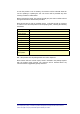
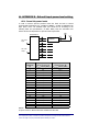
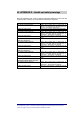
66.1. Down link power levels
In order to achieve spurious products below the limits set forth in various
governmental specifications (eg. -36 dBm for GSM900, –30 dBm for GSM1800) the
input power at the TFL downlink input port should be set according to the
following table. FCC specifications (-13 dBm- AMPS, PCS) are somewhat more
lenient and are also dependent on spectral mask requirements.
NUMBER OF
CARRIERS
(N)
Max power per carrier at
TFL DL RF input (a)
P
IN TFL
/carrier [dBm]
Max power per carrier at
TFA RF output (b)
P
OUT TFA
/carrier [dBm]
2 3,0 10,0
3 0,7 7,7
4 -0,3 6,7
5 -1,2 5,8
6 -1,8 5,2
7 -2,3 4,7
8 -2,7 4,3
9 -3,1 3,9
10 -3,4 3,6
11 -3,7 3,3
12 -4,0 3,0
14 -4,5 2,5
16 -4,9 2,1
18 -5,2 1,8
20 -5,6 1,4
22 -5,8 1,2
26 -6,4 0,6
30 -7,1 -0,1
34 -7,6 -0,6
40 -8,3 -1,3
NOTES:
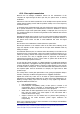
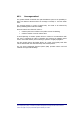
DL power levels for Britecell 900 MHz and Britecell 1800 MHz
TFLxxxx4H-x
TFL DL RF
input
TFL UL RF
output
a
b
b
TFAxxxx