
Install Manual


BRITECELL System Manual MN010-04 June 2003 Page 62 of 78
The company has a policy of continuous product development and improvement and we therefore
reserve the right to vary any information quoted without prior notice.
58. Installation and cabling
Britecell is designed to be simple and fast to install and commission. It requires a
minimum number of tools and equipment. However, it is necessary to observe
local regulations when planning and implementing an RF system and safety
conventions must be strictly adhered to at all times. One unique hazard with
Britecell is the presence of optical equipment; a thorough working knowledge of
optics, and the safety procedures in their use, is required by the installation,
commissioning and maintenance staff.
58.1. Local unit and subrack location
TFL Local Interface Units should be placed as near as possible to the BTS or the RF
repeater and should be easily accessible as they provide visual alarm information
for the system maintenance.
9
TPR 19" subrack needs proper air circulation. Take care that the operating
temperature range is met.
58.2. Remote unit and antennas location
The most efficient locations for the TFA Remote Transceivers will minimise the
number of antennas required, whilst maintaining the coverage level goal.
Please refer to the system design for the proper antenna location.
9
The position of the remote unit should be vertical to improve the thermal
dissipation.
9
There should be easy access to the optical and RF cables.
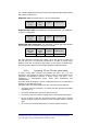
58.3. Fibre-Optic Cables
Britecell employs single-mode optic-fibre (SMOF) with the standard characteristic
dimensions of 9µm (core)/125µm (cladding).
The amount of protection needed by the fibre varies from one application to
another. A variety of cable designs are available to meet the requirements of
different installations. Here are some examples:
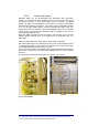
• Loose tube construction
: The fibre lies loosely inside a surrounding plastic
tube so that it can adjust itself when the cable is distorted; microbending
is almost completely eliminated by this technique. Loose tube cables are
preferred for long distance links and for almost all outdoor applications.
• Tight buffer construction
: the buffered fibre is completely enclosed in a
cushioning material (secondary coating up to an external diameter of
900µm) to improve crush resistance and vibration isolation, minimising
microbending. Tight buffer cables are usually adopted for indoor
applications because they offer small cross-section dimensions and small
bend radius.