
Install Manual


BRITECELL System Manual MN010-04 June 2003 Page 52 of 78
The company has a policy of continuous product development and improvement and we therefore
reserve the right to vary any information quoted without prior notice.
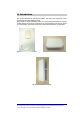
49.2. Description
TFB booster is a bi-directional RF amplifier designed to:
• improve the coverage area of the antennae connected to the remote unit
while maintaining same amount of distributed RF carriers;
or
• improve number of distributed RF carriers while preserving the same
coverage area.
Only single band version is available.
To enhance both RF ports of TFA remote unit, two TFB boosters are needed.
Downlink operation:
in downlink path, the booster performs an overall gain of 14
dB. ALC (automatic level control) circuit provides automatic limitation of excess
output power.
Uplink operations:
in uplink path, the booster has an overall gain of 4 dB, which
decreases the uplink noise figure (increasing system sensitivity).
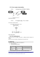
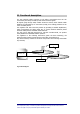
50. Alarms
TFB provides a logic alarm related to excess current draw. The alarm output must
be connected to TFA external alarm input , as shown in Fig. 37
Fig. 37
51. Installation and cabling
9
WARNING: for a proper connection of TFB to the Britecell system through the
TFA. Please refer to the system coverage design for additional information.
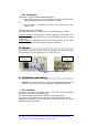
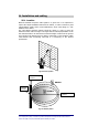
51.1. Location
TFB booster unit shall be installed close to TFA remote unit and radiating
antennas, as to minimise coaxial cable length.
The unit is intended to be installed on walls, flat or orthogonal surface.
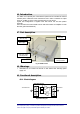
For a proper unit cooling take care of the warm unit side as indicated in Fig. 35
Installation must provide the correct positioning, and cables must be run so that
accidental damage is prevented.
TFB relay contact
(
out
p
ut
)
TFA relay contacts
(
in
p
ut
)