
Install Manual


BRITECELL System Manual MN010-04 June 2003 Page 33 of 78
The company has a policy of continuous product development and improvement and we therefore
reserve the right to vary any information quoted without prior notice.
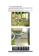
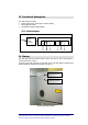
19.3. RF combined ports
These ports should be directly connected to the radiating antennas through RF
jumper cables.
Unused RF output ports must be terminated with a dummy 50Ω load. Optional
boosters (TFB family) also can be connected to one or both of the combined ports
for additional RF downlink power.
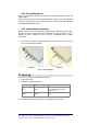
19.4. Optical fibres connection
Optical connectors need to have proper alignment and mechanical support. When
inserting an optical connector, take care to handle it smoothly enough so as not to
damage the fibre. Remove the dust cap only immediately before making
connections.
9
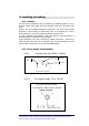
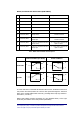
Do not force or stretch the fibre pigtail with curve radius less than 5 cm. See
Fig. 21 for optimal fibre cabling.
WRONG OPTIMAL
Fig. 21 - Fibre connection
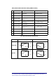
20. Start-up
To perform a preliminary verification of the TFA:
• power-up the TPA;
• verify the following LED status:
LED Colour Status
LD1 Red
OFF
if optical received power above
lower required limit and internal
operations ok
LD2 Green ON
For a full functionality test please refer to the system start-up section.