
Install Manual


BRITECELL System Manual MN010-04 June 2003 Page 32 of 78
The company has a policy of continuous product development and improvement and we therefore
reserve the right to vary any information quoted without prior notice.
19. Installing and cabling
19.1. Location
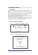
TFA units shall be installed as close as possible to the radiating antennas, so as to
minimise coaxial cable length and reduce downlink power loss and uplink noise
figure.
However, the units should be installed no closer than 2.5 m to the closest mobiles
approach to avoid blocking. If remote units need to be installed very close to
where mobiles are, the internal variable attenuator should be used.
The TFA is intended to be installed on walls, false ceilings or other flat surfaces. A
mounting bracket is available for easy mounting.
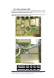
Proper installation of the TFA is required for optimal performance. Take care to
install the TFAs "warm side out" as indicated in Fig. 14 The positioning of the unit
and the cables is important so as to avoid accidental damage.
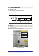
19.2. Power supply and grounding
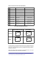
19.2.1. Universal mains (85-264VAC, 50/60Hz)
Fig. 19 -Mains connector
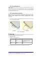
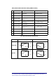
19.2.2. DC negative supply –72 to –36 VDC.
Fig. 20 - VDC connector
mains
mains
GROUND
DC connector and part number: