
Install Manual


BRITECELL System Manual MN010-04 June 2003 Page 31 of 78
The company has a policy of continuous product development and improvement and we therefore
reserve the right to vary any information quoted without prior notice.
18.3. Setting uplink gain (PGR)
To optimise system performances related to “blocking level” (refer to system
design for further details), TFA units shall include an RF uplink attenuator to adjust
the uplink gain (Pre-settable Gain Reduction – PGR).
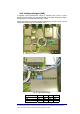
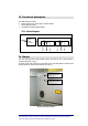
Up link gain setting can be easily executed removing the rear lid (see Fig. 17) and
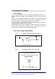
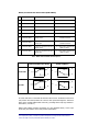
setting SW1 bits (see Fig. 18) according to Tab. 5.
Fig. 17 – TFA PGR dip- switches
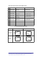
Fig. 18 – Dip-switches settings
Gain Reduction bit 1 bit 2 bit 3 bit 4
0 dB OFF OFF ON OFF
5 dB OFF ON OFF OFF
10 dB ON OFF OFF OFF
Tab. 5 - Uplink gain reduction settings