
Install Manual


BRITECELL System Manual MN010-04 June 2003 Page 30 of 78
The company has a policy of continuous product development and improvement and we therefore
reserve the right to vary any information quoted without prior notice.
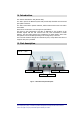
17.3. Up link operations.
In the uplink the TFA performs the following functions:
Filtering & Amplification:
a filter delimits the uplink band and a low noise amplifier increases the
signal level to minimise the noise figure of the link.
E/O Conversion:
the RF signal coming from the antennas modulates the intensity of an
optical carrier through a laser.
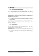
18. Alarms and settings
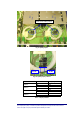
18.1. LED alarms
For TFA units only visual alarms are provided. Two LEDs represent them:
LED Colour Meaning (when lit)
LD1 Red
No optical power at DL input and/or
amplifier failure
LD2 Green Power supply is on
Tab. 4 – TFA Alarm LEDs
NOTE:
the uplink laser is on only if downlink optical signal is present and
no failure occurs in the TFA; in case of any failure, the uplink laser is
switched off.
It is useful to note that as a downlink failure will be reported to both TFL a TFA, it
is possible to determine a fibre or TFA failure from either the TFA or TFL.
This information can be used in conjunction to others for troubleshooting (see
par.21).
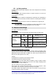
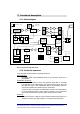
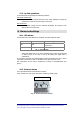
18.2. External alarms
TFA is provided with two external alarm contacts.
These contacts are open under non-alarm condition (normally open).
Fig. 16 - External alarms (dry contacts)
Alarm when closed