
Install Manual


BRITECELL System Manual MN010-04 June 2003 Page 29 of 78
The company has a policy of continuous product development and improvement and we therefore
reserve the right to vary any information quoted without prior notice.
17. Functional description
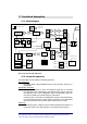
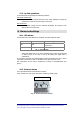
17.1. Block diagram
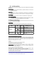
Fig. 15 – TFA block diagram
Note 1: not present in UHF TDD version
17.2. Down link operation
In the downlink the TFA fulfils the following operations:
O/E Conversion:
the optical signal is demodulated through an opto-electronic device (p-i-n
photodiode).
Amplification & Filtering:
amplification is required to boost the downlink signal after is converted
from light back to RF. Maintaining a good signal-to-noise ratio is critical for
this operation; part of the amplification process automatically takes into
account the variable loss introduced by the optical fibre.
A clean-up filter is used after the amplification process to limit transmission
to the downlink band and to reduce spurious emissions in the uplink band
where they would interfere with the signal coming from the mobile.
Duplexing:
the RF signal enters a duplexer which combines downlink and uplink on a
single port which is then split and goes to two separate antenna ports.
PHOTODETECTOR
LNA AMP
Paging RF SMA
connector 50 Ω
VOLTAGE
CONTROLLED
ATTENUATOR
AMP
AMP
AMP
AMP
AMP
AMP
VARIABLE
GAIN
AMP.
D
A
C
A
D
C
µPROC.
4 MHz
Diff. AMP
NOISE
GENERATOR
LASER module
MONITOR
PHOTODET.
LASER DIODE
VOLTAGE
CONTROLLED
ATTENUATOR
AMP
AMP
MATCHING
NETWORK
UL ATTENUATOR CONTROL
SWITCHES
attenuator
control
voltage
DL final amplifier stage
current monitor
LNA
AMP
LNA
Green LED:
power on
Red LED: UL
final amplifier
stage current
out of allowed
range or low
o
p
tical
p
ower
RF N
50 Ω
RF N
50 Ω
POWER SUPPLY
UNIT
AC input from
mains
DC/DC
converter
Voltage
Regulator
RX optical power monitor
Attenuator
control voltage
DL final amplifier stage out
of allowed range
Threshold
circuit
with
adjustable
threshold
level.
Low RX optical
power
CURRENT
GENERATOR
OR
circuit
LASER control
module
+12 V
-8 V
+5 V
Internal LED: DL
final amplifier
stage out of
allowed ran
g
e
External Booster alarms
(note1)