
Install Manual


BRITECELL System Manual MN010-04 June 2003 Page 24 of 78
The company has a policy of continuous product development and improvement and we therefore
reserve the right to vary any information quoted without prior notice.
11.4. Optical connections
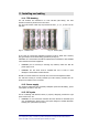
Optical connectors are designed to have proper alignment and mechanical support.
When inserting an optical connector, take care to handle it smoothly enough so as
not to damage the fibre.
Fasten the fibre cable to the provided seating base by means of the included
wrapper.
Remove the dust cap only immediately before making connections.
9
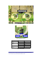
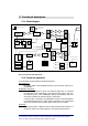
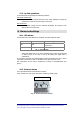
Do not force or stretch the fibre pigtail with curve radius less than 5 cm. See
Fig. 13 for optimal fibre cabling.
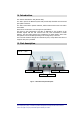
Fig. 13 – Fibre connection
12. Start-up
A preliminary verification of TFL correct operation is:
1. switch-on the TPR subrack
2. verify the following LED status
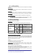
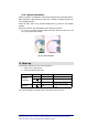
Link LED Colour Status
= Green ON
Red OFF
Downlink
Transmitter
OFF Yellow OFF
Uplink
receivers
Red
Depending upon TFA status,
always off if receiver alarm
disabled
For a full functionality test please refer to the system start-up section.
WRONG OPTIMAL