
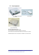
Install Manual


BRITECELL System Manual MN010-04 June 2003 Page 18 of 78
The company has a policy of continuous product development and improvement and we therefore
reserve the right to vary any information quoted without prior notice.
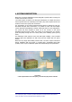
6. Introduction
This section describes the TFL (Local Unit). The TFL is the part of Britecell system
that provides E/O downlink conversion and O/E uplink conversion of RF signal.
The TFL is connected to remote TFA by means of two optical fibres.
The system forms a star configuration. One fibre is dedicated to the transmission
of the downlink signals received from BTS and re-transmitted to the mobile. The
other fibre supports the transmission of up-link signals, received from mobile
through the TFA remote units and destine for the BTS.
The TFL cards are 6HE plug-in modules and are contained in a standard 19”
subrack (TPR family).
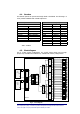
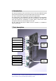
7. Part description
Fig. 7 – TFL Local Unit part description
Power Supply led (green)
DL Laser Alarm (red)
DL RF Test Port (SMB-m)
DL RF Input (SMA-f)
Dummy (used in other application)
Uplink
Optical
Connectors
UL Alarm leds (red)
UL RF Test Port (SMB-m)
UL RF Output (SMA-f)
Backplane
Connector
Downlink
Optical
Connectors
Laser off led (yellow)
UL Alarm leds (red)