
Install Manual


BRITECELL System Manual MN010-04 June 2003 Page 14 of 78
The company has a policy of continuous product development and improvement and we therefore
reserve the right to vary any information quoted without prior notice.
4.3. Functional description
The basic system blocks are the fiber donor unit TFL (Local Unit) and the fiber
remote unit TFA (Remote Unit).
They are connected in both directions (uplink and downlink) through single mode
optical fibre.
The system has a built-in Automatic Gain Control (AGC), which automatically
adjust the up link and down link gain in order to compensate for optical link loss
1
.
This allows the downlink transmit power and the up link sensitivity to be virtually
independent on fibre length and on the number of splices or optical connectors
present along the fibre link.
Each Local unit can support and constantly monitor up to 4 remote units.
Moreover up to 6 central units can be housed, together with power supply, in the
same subrack 19”.
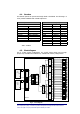
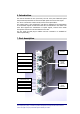
The TFA feeds up to two coverage antennas. In this way it is possible to set up a
network of 24 transceivers and up to 48 coverage antennae (see Fig.2).
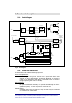
The connection between the BTS and Britecell system can either be direct or,
through a repeater.
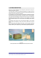
In Fig. 1, a typical direct connection to BTS is showed for a dual band system. The
building blocks of the combining network are:
• two/three way combiners and splitters (TLC2502/3);
• cross-band couplers (TLC2501);
• variable attenuators (TFL-BSI).
The combining network has to be carefully designed in order to optimise the
connection to the BTS and the system performances.
1
provided that the specified limits are not exceeded
(please refer to datasheets)