
User Manual


BRITECELL System Manual MN010-04 June 2003 Page 23 of 78
The company has a policy of continuous product development and improvement and we therefore
reserve the right to vary any information quoted without prior notice.
11. Installing and cabling
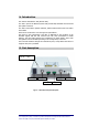
11.1. TPR housing
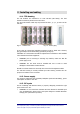
The TFL modules are contained in a 6 HE sub-rack (TPR family). The local
interfaces cannot be placed next to each other.
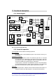
The TFL local interface cards may only be fitted in slots 1, 3, 5, 7, 9, and 11 of the
sub-rack.
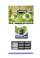
Fig. 11 - Subrack slots Fig. 12– Dummy plug
If any slots are unused the backplane connectors must be fitted with a dummy
plug (provided) to avoid alarms being generated (see Fig.15).
Installation of Local Interface should be implemented in accordance with standard
rules related to fixed base equipment.
9
WARNING: prior to removing or inserting any modules, make sure that the
power supply is off.
9
WARNING: the TFL cards must be handled with care in order to avoid
damages to electrostatic sensitive devices.
Should a Local Unit need to be removed, first remove the left adjacent module.
The sub-rack housing if correctly installed (see TPR section) provides also the
proper air circulation to the Local Unit.
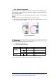
11.2. Power supply
TFL cards are powered by the proprietary backplane (Sub-rack TPR family), power
consumption is 12W for each TFL.
11.3. RF inputs
The RF combining and interface section, if properly designed, provides the right
power levels to the TFL.
9
WARNING: Do not exceed the maximum RF level allowed for downlink input
(see TFL datasheets). Please refer to the system design for variable attenuator
settings (see system start-up section)